Motor Control Circuit Forward Reverse | Wiring and Connection
Hi, in this article we are going to see Motor Control Circuit Diagram to rotate in Forward and Reverse Direction. Here, the wiring diagram and control circuit diagram both are given and explained in detail. Generally, in industrial applications, Elevators, Cranes, etc we need to rotate the motor in both forward and reverse directions.
Forward Rotation or Clockwise(CW) Rotation:
Generally, three-phase electrical motors are designed or their windings are connected in such a way that when R, Y, and B phases are connected with motor terminals R, Y, B or U, V, W or T1, T2, T3 respectively then they will run in Forward Direction or Clockwise.
Reverse Direction or Anti Clockwise(ACW) Rotation:
We know that in a three-phase electric motor, if we interchange any two terminals of the motor or power supply, it will rotate in the reverse direction. So this basic concept is used in this circuit diagram.
Forward Reverse Motor Control Wiring Diagram
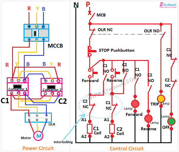
Here the wiring diagram for motor control with indicator light connection is given below.
Different Parts and Equipment:
MCCB
Here MCCB or Moulded Case Circuit Breaker is used as the main incoming breaker which provides a switching function and protection against short circuit faults.
Control MCB
A single-pole MCB is used for the control circuit and its incoming is taken from the incoming 'R' phase.
Contactor
Here you can see two pieces of electrical contactors are used. One is for forward-direction rotation and the other one is for reverse-direction rotation.
Thermal Over Load Relay
Here a 3-pole thermal overload relay is used. This relay has one NO contact and one NC contact.
Push Button Switch and Indicator Lamp
Here three push button switches are used - Forward, Reverse, and Stop. Total four PCs indicator lamps are used - Forward, Reverse, Stop, and Trip
Connection Description
1. The main incoming three-phase supply is connected to the MCCB. MCCB outgoing is connected to the contactor.
2. Here both contactor is connected in parallel but the 'R' and 'B' phases are interchanged for the second contactor.
3. Interlocking: The arrangement of turning on only one contactor at a time is called interlocking. As both contactors are connected in parallel and the terminal interchanged for the second contactor, so there will be a short circuit if both contactors are turned on at the same time.
So the magnetic coil of the first contactor is connected through the NC contact of the second contactor. As it is the magnetic coil of the second contactor is connected through the NC contacts of the first contactor. So only one contactor can be turned at a time.
4. Here, you can also see the main incoming of the control circuit is connected through the NC contact of the thermal overload relay, so when the relay turns On due to an overcurrent fault it will disconnect the total control circuit from the power supply as a result contactor also be turned off and the motor will be disconnected from the power supply.
Power Control Circuit Diagram for Motor Control in Forward and Reverse Direction
Read Also:
Thank you for visiting the website. keep visiting for more updates.


