Working and connection diagram of Single Phasing Preventer
Single Phasing and Single Phasing Preventer
In this post, we are going to learn a very important topic in electrical engineering that is What is Single Phasing? Working and connection of Single Phasing Preventer.
Before going to read about Single Phasing Preventer, you must know about What is single Phasing?
What is Single Phasing?
When a three-phase motor is running, if one phase among three phase is open-circuited then it is called Single Phasing.
We know that a three-phase motor is more efficient than a single-phase motor. Each three-phase motor has either a star or a delta connection. So if one of the phases is open they will continue to run but they will be drawn approximately 2.5 times the normal current during the single phasing condition.
So basically, absence of one phase among the three phases is called Single Phasing.
Why we need Single Phasing Preventer?
You may think that as the motor will continue to run after a single phasing, then why do we need a Single Phasing Preventer.
We need Single Phasing Preventer because as after single-phasing, the motor will draw current 2.5 times of the normal current so motor windings may get damaged even may burn.
There are many bad effects of single phasing, so we need a Single Phasing Preventer.
How a Single Phasing Preventer works?
Basically, a Single Phasing Preventer works like a switch, but it automatically closes the circuit in normal conditions and opens the circuit in the fault condition that is single-phasing.
For better understanding see the below circuit diagrams. There are two circuit diagrams are given below. One diagram is for the normal conditions and the other is for the fault condition.
Types of Single Phasing Preventer:
(1) Voltage sensing Single Phasing Preventer.
(2) Current sensing Single Phasing Preventer.
What inside a Single phasing Preventer?
Here a voltage sensing single phasing preventer is shown. as you see in the below picture it consists of a 12V Relay, a 440V/12V transformer for operating the Relay, PN junction diodes for the bridge rectifier, some capacitors, transistors, Zener diodes, resistors, variable resistors.
click on the image to enlarge
Connection diagram of The Single Phasing Preventer:
The Single Phasing preventer which is shown in pictures has Five terminals, three terminals red, yellow, and blue for three phase supply which are to be connected before the motor and after the contactor. The remaining two gray terminals are the 'Common terminal' of the relay and the 'Normally closed (NC) terminal' of the relay. As you see in the below connection diagrams the Contactor having the rating 230V. So an auxiliary supply of 230V is given to the Contactor through the two terminal of the Single Phasing Preventer.
Under Normal Condition:
In normal condition the preventer act as a closed switch therefor the contactor is connected to 230V supply and holds the circuits closed so the motor will be run.
Click on the image to enlarge.
Under Fault Condition:
When the 'R' phase gets disconnected or single phasing occurred the preventer sens the fault and act as an opened switch therefor the Contactor not get supply and it breaks the circuits so the motor will be stopped.
Click on the image to enlarge.
This was the single phase preventer circuit and connection diagram with three-phase motor and Contactor.
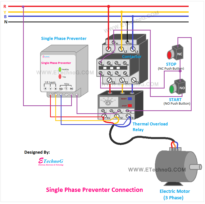
Single Phase Preventer Connection and Wiring Diagram
So, you can follow the above wiring diagram and the below connection procedure to connect your own Single Phase Preventer,
- Connect all the three phases from the output of the contactor that is going to the motor to the three-phase input terminal of the single-phase preventer.
- Connect the coil of the contactor to through the NC contacts of the single phase preventer and the thermal overload relay.
These are the main key points to keep remembering while making the connection, other all the connections can be done according to the above connection diagram.
- Phase Sequence Relay Wiring Diagram and Connection
- Earth Leakage Relay Wiring and Connection Diagram
- Shunt Trip Breaker Wiring Diagram, Connection, Circuit
- MPCB Uses, Advantages, Connection | Motor Protection Circuit Breaker
- Contactor Interlocking Circuit and Wiring Diagram
- Proper RCCB connection Diagram with MCB
- Motor Control Circuit Forward Reverse | Wiring and Connection
Thank you for visiting the website. keep visiting for more updates.


.jpg)
.jpg)
