Shunt Trip Breaker Wiring Diagram, Connection, Circuit
Hey, in this article we are going to see a shunt trip breaker wiring diagram. From this diagram, you will learn how to do a shunt trip breaker connection for an MCCB. Generally, this arrangement is used for MCCB or Moulded Case Circuit Breaker. So, here you will get the MCCB Shunt Trip Breaker Circuit also.
What is Shunt Trip Breaker?
A shunt trip breaker is a specially designed circuit to trip the MCCB manually by the applied a power supply to its shunt trip coil.
The shunt trip coil is an optional accessory that can be installed in certain MCCBs. It consists of a coil of wire that is energized when a specific control signal is received. When energized, the shunt trip coil creates a magnetic field that releases the trip mechanism of the MCCB, causing it to open and interrupt the circuit. Not all the MCCBs have a shunt trip coil, as it is an optional feature. The presence of a shunt trip coil in an MCCB depends on the specific model and its intended application. The control signal to energize the shunt trip coil can be generated by various devices, such as manual switches, remote control systems, fire alarm systems, or other safety devices.
The main function of an MCCB is to protect the circuit or equipment from overload or short circuit faults. So, the MCCB will trip automatically when a short circuit or overload fault occurs. But for some emergency purpose, we need to off the MCCB immediately.
Suppose, your MCCB is fixed far away from the load circuit. So, if any fault happens with the load, how do you off the MCCB immediately. Here, the shunt trip breaker comes in the application.
Shunt Trip Breaker Wiring Diagram and Connection
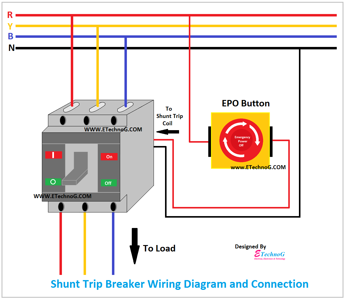
Here, you can see the wiring diagram of shunt trip breaker.
Read Also:
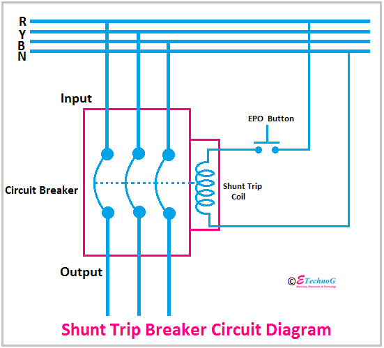
This is a very simple wiring diagram. You can see just there is an EPO or Emergency Power Off button is connected in series with the shunt trip coil of the MCCB. The EPO switch is a manually operated switch or button typically located in easily accessible areas such as emergency exits or control rooms. When activated, the EPO switch sends a control signal to the shunt trip coil of the MCCB, causing it to trip and disconnect power from the connected circuit. It is a normally open switch, when you push, it will close the circuit. So the shunt trip coil will get a power supply and it will trip the MCCB.
Note that, the shunt trip coil is rated for 230V. That's why it is connected with the 'R' phase and neutral.
Generally, this EPO button is fixed near the load or near the operator of the machine. So, the operator can easily press the button to stop the power supply in emergency cases.
Connection Procedure
Remember that here the trip coil in the MCCB is rated for 230V single-phase supply.
1. Connect the neutral wire of the power supply to anyone terminal of the shunt trip coil. If, its terminals are identified, then connect to the neutral terminal.
2. Connect any one terminal of the EPO button to any one phase of the power supply from the output of the MCCB.
3. Connect another terminal of the EPO button to the rest terminal of the shunt trip coil.
Shunt Trip Breaker Circuit Diagram
Here, you can see the circuit diagram of shunt trip breaker.
This type of circuit arrangement is used in Certain critical systems or equipment, such as industrial machinery, data centers, or medical facilities, and may require an immediate shutdown in emergency scenarios. The integration of the shunt trip coil with the EPO switch allows for quick power interruption to prevent further damage or hazards.
Read Also:


