Tunnel Light Wiring Diagram and Connection Procedure
Here, in this article, we are going to see the complete wiring diagram for installing multiple lights in Tunnel. Also, we will know the connection procedure and operating principles.
Tunnels are generally dark and confined spaces where natural light from the sun is absent. Installing multiple lights ensures that the tunnel interior is well-designed, allowing drivers, cyclists, and other travelers to see clearly and navigate safely.
Along the tunnel walls and ceiling, light fixtures are mounted at regular intervals. The fixtures may be high-intensity discharge (HID) lamps, fluorescent tubes, LED lights, or any other type of lighting suitable for tunnel environments.
Nowadays, tunnels have advanced lighting control systems that allow for dimming or adjusting the intensity of the lights based on traffic conditions, time of day, or ambient light levels. These systems require additional wiring and control interfaces. Here, we are going to see the basic wiring diagram with two-way or SPDT switches.
Wiring Diagram
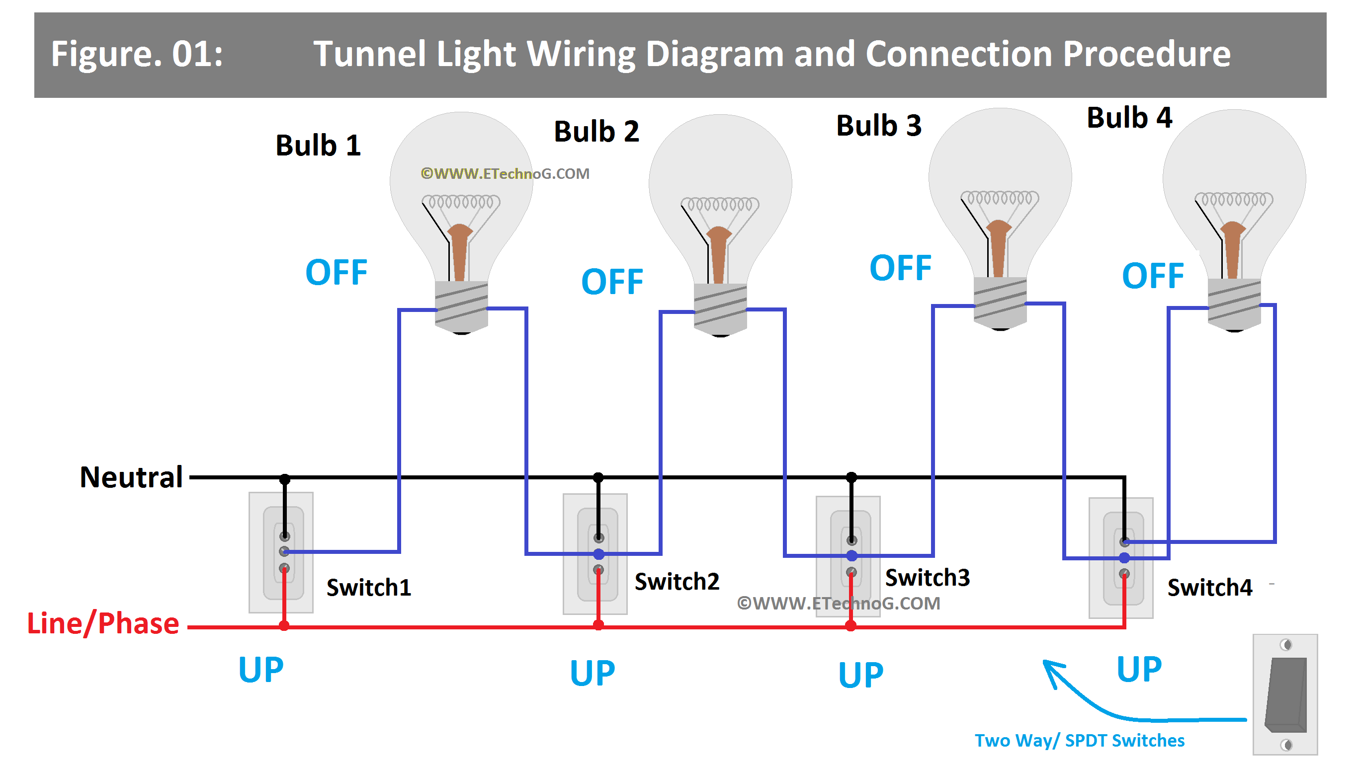
Here, you can see the complete wiring diagram of Tunnel Lights with Two Way Switches. Here, we have used four lamps only to simplify the diagram and easy to understand.
Read Also:
Connection Description
1. All the two-way switches are connected in parallel with the power supply. Here neutral from the power source is connected to the upper terminal of all the two-way switches and the live or phase terminal from the power source is connected to the lower terminal to all the two-way switches.
2. One terminal of the Bulb 1 is connected to the Common(middle) terminal of Switch 1. And the other terminal of the Bulb 1 is connected to the Common(middle) terminal of Switch 2.
3. One terminal of the Bulb 2 is connected to the Common(middle) terminal of Switch 2. And the other terminal of the Bulb 2 is connected to the Common(middle) terminal of Switch 3.
4. One terminal of the Bulb 3 is connected to the Common(middle) terminal of Switch 3. And the other terminal of the Bulb 3 is connected to the Common(middle) terminal of Switch 4.
5. One terminal of the Bulb 4 is directly connected to the neutral. And the other terminal of the Bulb 4 is connected to the Common(middle) terminal of the Switch 4.
Operation Principle
Here, are the operating principle or position of each switch to turn on and turn off different bulbs.
Turn off all the Bulbs
As you already see in the above wiring diagram(figure. 01), all the lamps will be turned off when the switches have the following positions.
Switch 1: Up
Switch 2: Up
Switch 3: Up
Switch 4: Up
Turn On Bulb 1
Bulb 1 will be turned on when the switches have the following positions.
Switch 1: Down
Switch 2: Up
Switch 3: Up
Switch 4: Up
Turn On Bulb 2
Bulb 2 will be turned on when the switches have the following positions.
Switch 1: Down
Switch 2: Down
Switch 3: Up
Switch 4: Up
Turn On Bulb 3
Bulb 3 will be turned on when the switches have the following positions.
Switch 1: Down
Switch 2: Down
Switch 3: Down
Switch 4: Up
Read Also:
Turn On Bulb 4
Bulb 4 will be turned on when the switches have the following positions.
Switch 1: Down
Switch 2: Down
Switch 3: Down
Switch 4: Down
Turn On Bulb 1 and 4
Bulbs 1 and 4 will be turned on when the switches have the following positions.
Switch 1: Up
Switch 2: Down
Switch 3: Down
Switch 4: Down
Turn On Bulb 2 and 3
Bulbs 2 and 3 will be turned on when the switches have the following positions.
Switch 1: Up
Switch 2: Up
Switch 3: Down
Switch 4: Up
Turn On all the Lamps
All the Lamps will be turned on when the switches have the following positions.
Switch 1: Up
Switch 2: down
Switch 3: Up
Switch 4: Down
Read Also:


.png)
.png)
.png)
.png)
.png)
.png)
.png)