RLC Parallel Resonance Calculator (Frequency, Bandwidth, and More)
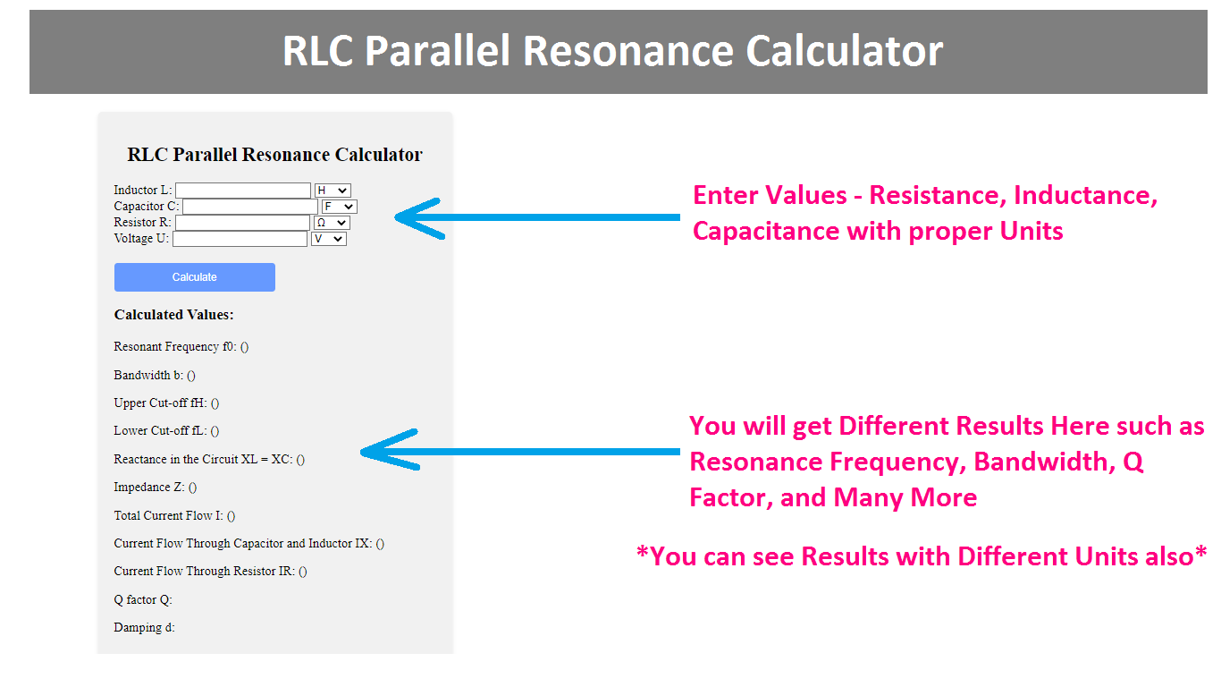
Here using this RLC Parallel Resonance Circuit Calculator, you can calculate Impedance(Z), Resonant Frequency(f0), Upper Cut-off Frequency(fH), Lower Cut-off Frequency(fL), Bandwidth(b), Q factor(Q), Damping(d), and many more Parameters.
RLC Parallel Resonance Calculator
Calculated Values:
Resonant Frequency f0: ()
Bandwidth b: ()
Upper Cut-off fH: ()
Lower Cut-off fL: ()
Reactance in the Circuit XL = XC: ()
Impedance Z: ()
Total Current Flow I: ()
Current Flow Through Capacitor and Inductor IX: ()
Current Flow Through Resistor IR: ()
Q factor Q:
Damping d:
How to Use This Calculator?
To use the above "RLC Parallel Resonance Calculator," follow the below steps,
1. Enter the value of the inductor (L) in the first input field. Select the appropriate unit from the dropdown menu (H for henries, mH for millihenries, or μH for microhenries).
2. Enter the value of the capacitor (C) in the second input field. Select the appropriate unit from the dropdown menu (F for farads, μF for microfarads, nF for nanofarads, mF for millifarads, or pF for picofarads).
3. Enter the value of the resistor (R) in the third input field. Select the appropriate unit from the dropdown menu (Ω for ohms, mΩ for milliohms, kΩ for kilohms, or MΩ for megaohms).
4. Enter the value of the voltage (U) in the fourth input field. Select the appropriate unit from the dropdown menu (V for volts, mV for millivolts, or KV for kilovolts).
5. After filling in all the required values, click on the "Calculate" button at the bottom of the form.
6. Once you click on the "Calculate" button, the calculator will process the input data and display the value of different parameters of the RLC Parallel Resonance Circuit.
Formula
Here are the formulas the above calculator uses to perform the calculations,
Resonant Frequency (f0):
resonant frequency = 1 / (2 * π * √(L * C))
Reactance in the Circuit (XL = XC):
reactance = 2 * π * resonant frequency * L
Impedance (Z):
impedance = R
Total Current Flow (I):
total current = U / Z
Current Flow Through Capacitor and Inductor (IX):
IX = U / reactance
Current Flow Through Resistor (IR):
IR = U / R
Q Factor (Q):
Q factor = Resistance/reactance
Damping Factor (d):
Damping = 1 / Q factor
Bandwidth (b):
bandwidth = resonant frequency / Q factor
Upper Cut-off Frequency (fH):
fH = resonant frequency + (bandwidth / 2)
Lower Cut-off Frequency (fL):
fL = resonant frequency - (bandwidth / 2)
What is RLC Parallel Resonance Circuit?
An RLC Parallel Resonance Circuit is also known as a parallel resonant circuit. It is an electrical circuit that consists of three passive components connected in parallel such as a resistor (R), an inductor (L), and a capacitor (C). In this circuit configuration, all three components share the same two nodes or junction points, forming a parallel arrangement.
In an RLC Parallel Resonance Circuit, the inductor and capacitor together create a resonant circuit, which means they have a specific resonant frequency at which the circuit provides some interesting properties. When the frequency of the applied voltage matches the resonant frequency of the circuit, it results in resonance.
At the resonant frequency, the reactance of the inductor (XL) becomes equal to the reactance of the capacitor (XC) which causes a minimum impedance. The circuit becomes purely resistive, and the current flow is at its maximum.
Like Series Resonance circuits the RLC Parallel Resonance Circuits are also used in various applications in various fields, such as filter design, communication systems, and tuning circuits.
Related Calculators:
- Series-Parallel Impedance Conversion Calculator
- Resonant Frequency Calculator
- RLC Series Resonance Calculator (Frequency, Bandwidth, and More)
- LC Resonance Circuit Calculator (Component Rating, Frequency)
- RLC Parallel Circuit Calculator (Impedance, Reactance, and More)
- RLC Series Circuit Calculator (Impedance, Reactance, and More)
- Series and Parallel Capacitor Calculator (Add Unlimited)
- Series and Parallel Inductor Calculator (Add Unlimited)
- Series and Parallel Resistor Calculator(Add Unlimited)
- Wheatstone Bridge Calculator (Balanced and Unbalanced)
- Explore all 100+ Electrical and Electronic Calculators

