Electrical Extension Board Connection Diagram and Wiring
Hey, in this article we are going to see the connection diagram of an electrical extension board and its wiring. An extension board is a type of electrical power distribution board built with some power sockets, switches, and some other additional devices. If you are an electrical professional then you can easily make an extension board at your home. Extension boards are very useful for providing electrical multiple devices when we have a limited power socket in our general switchboard.
For, example, in your switchboard, only one power socket is there. But you have a table fan, TV, and Music player. How to connect them. Use an extension that has at least three power sockets so you can connect all those three devices for use at the same time. Extension boards are not only used for indoor use but also used for outdoor work also.
Extension Board Connection Diagram
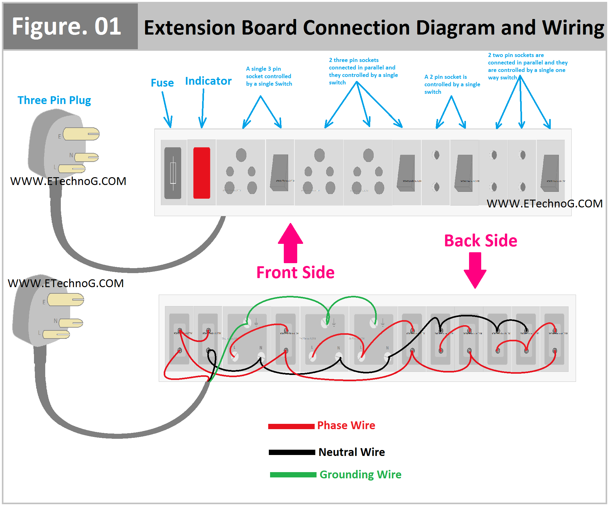
Here, you can see the connection diagram of the Extension Board.
Of course, when you make an extension board, your goal may be different. You may not want to make an extension board like that shown in the below figure. So, we have designed the above extension board in such a way that it has all types of components and connection procedures that will help you to make any type of board as per your requirement. For example, here we have shown both types of power sockets 2 pins and 3 pins. So if you using any one type of them, then follow the connection procedure of those particular types.
Also, you can see we have shown the connection of a single power socket with a single switch and multiple power sockets with a single switch. So if you use a single power socket with a single switch then follow the particular connection procedure. But if you want to connect multiple power sockets in parallel and control them using a single switch also you can follow the above diagram.
Required Components
Power Socket - There are two types of power sockets used to make an extension board - 2-pin (input), and 3-pins (input). Three-pin sockets required all the phase, neutral, and grounding connections whereas two-pin sockets required only phase and neutral connections. Generally, 6A power sockets are used for extension boards, but you can use 16A power sockets also if you require them. But in this case, the rating of the fuse and the size of the cable should be changed.
Switch - The piano-type one-way SPST switch is used to make the extension board. Use the 6A switch for the 6A power socket and use the 16A switch for a 16A power socket.
Fuse - Power sockets and switches are the main components of an extension board but for safety purposes, you can use a fuse also. Use 6A or 16A Fuse as per your output required.
Indicator - A red color indication lamp also can be used to indicate if the board has a power supply or not.
Connection and Wiring Procedure
- Connect the phase wire from the input cable directly to the fuse. That means the fuse should be connected in series with the input phase terminal and switches.
- Connect the output of the fuse to all the switches using jumper wires.
- If you do not use a fuse then you can connect the input phase wire directly to the switches.
- If you use the indicator then connect the phase terminal of the indicator(any one terminal if there is no marking) to the output of the fuse.
- Connect the neutral wire from the input cable to the indicator and all the neutral terminals of the power sockets.
- Generally, the neutral terminal is marked as 'N' in the power sockets. If there is no identification, then connect the neutral wire to the downside terminal of the 2-pin socket and connect the down-right side terminal of the 3-pin socket( when you see from the backside the neutral terminal will be on the right side but when you see from the front side the neutral terminal will be in the left side).
- Connect the phase or live terminal of the power sockets to their respective switches. When you connect multiple sockets with a single switch then the phase terminal of all those sockets are to be connected together and finally to the switch.
- Connect the grounding wire from the input cable to all the power sockets that have the grounding terminal.
Read Also:

