Exhaust Fan Wiring Diagram and Connection with Capacitor
Hey, in this article, we are going to see the wiring diagram of Exhaust fan and connection with the Capacitor, Two Way Switch for Forward and Reverse Rotation. Here, we will see the wiring diagram of a single-phase exhaust fan that uses a single-phase AC Motor.
An exhaust fan is a type of mechanical ventilation system used to remove unwanted dust particles, pollutants, and moisture from indoor spaces. It is commonly found in kitchens, bathrooms, and other enclosed areas where ventilation is necessary to maintain air quality and prevent the buildup of humidity and condensation. The primary function of an exhaust fan is to expel stale or contaminated air from the room and replace it with fresh outdoor air. This process helps in maintaining a healthy and comfortable living environment.
Wiring Diagram
Here, you can see the Exhaust Fan Wiring Diagram and Connection with Capacitor, Two Way Switch, Plug Top, etc.
See Also:
Connection Description
1. The exhaust uses a single-phase induction motor that has three terminals - Common(Black), starting(Yellow), and Running(Red). In some fans, Red color is used for the common, and black color is used for running. So check your fan.
2. The three-pin Plug top is used to connect the fan to a power socket from where the fan will take the electrical power supply.
3. The phase or line terminal from the plug top is connected to the middle or common terminal of the Two Way Switch.
4. The neutral terminal from the plug top is connected to the Common or black terminal of the exhaust fan motor.
5. The capacitor is connected across the starting(yellow) and running(red) terminal of the fan motor.
6. Now the running terminal is connected to the lower terminal of the two-way switch.
7. The starting terminal is connected to the upper terminal of the two-way switch.
8. The grounding terminal from the plug top is to be connected to the metallic body of the fan.
**Remember that Exhaust fan from different manufacturer has different identifications and color codes. So follow the user manual provided by the manufacturer before making the connection.**
Working Principle
The working principle of the exhaust is very simple. When you turn on the power supply it works like a ceiling fan works.
Here, you just need to know the function of the two-way switch. The two-way switch is basically used to change the rotation of the fan either in reverse or forward direction.
As you can see, one terminal of the switch is connected to the running terminal, and one terminal is connected to the starting terminal. So when we operate the two-way switch the line terminal from the power source is connected to either the running terminal or the starting terminal.
As per the above diagram, when we press the switch on the upper side the phase supply will be connected to the starting terminal and the fan will rotate in the clockwise or forward direction. when we press the switch on the bottom side the phase supply will be connected to the running terminal and the fan will rotate in the anti-clockwise or reverse direction.
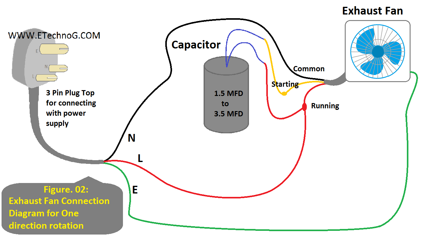
Connection Diagram for One Direction Rotation
If you don't want forward and reverse rotation then you do not need to connect the two-way switch. Just connect the line terminal from the plug top directly to the running terminal and keep all the rest connection as it is. Follow the below connection diagram.
See Also:


