Micro USB Pinout Diagram | Type A, B, C
USB stands for Universal Serial Bus. It is basically an interfacing system available in the form of connectors or ports to make communication between computers and the peripheral. The USB port is the most usable than others. It helps to transfer both data and electrical power. You can find the applications of USB ports in computers, laptops, smartphones, printers, scanners, cameras, and many more digital devices.
USB Ports and connectors come in so many types such as Standard USB, Mini USB, and Micro USB. In this article, we are going to know about Micro USB. Micro USB is basically designed for compact and portable devices such as mobile phones, mp3 players, cameras, USB lights, GPS devices, Video game controllers, etc. Here you will get the pinout diagram of all three types of micro USB pins or connectors.
Type A Micro USB Pinout Diagram
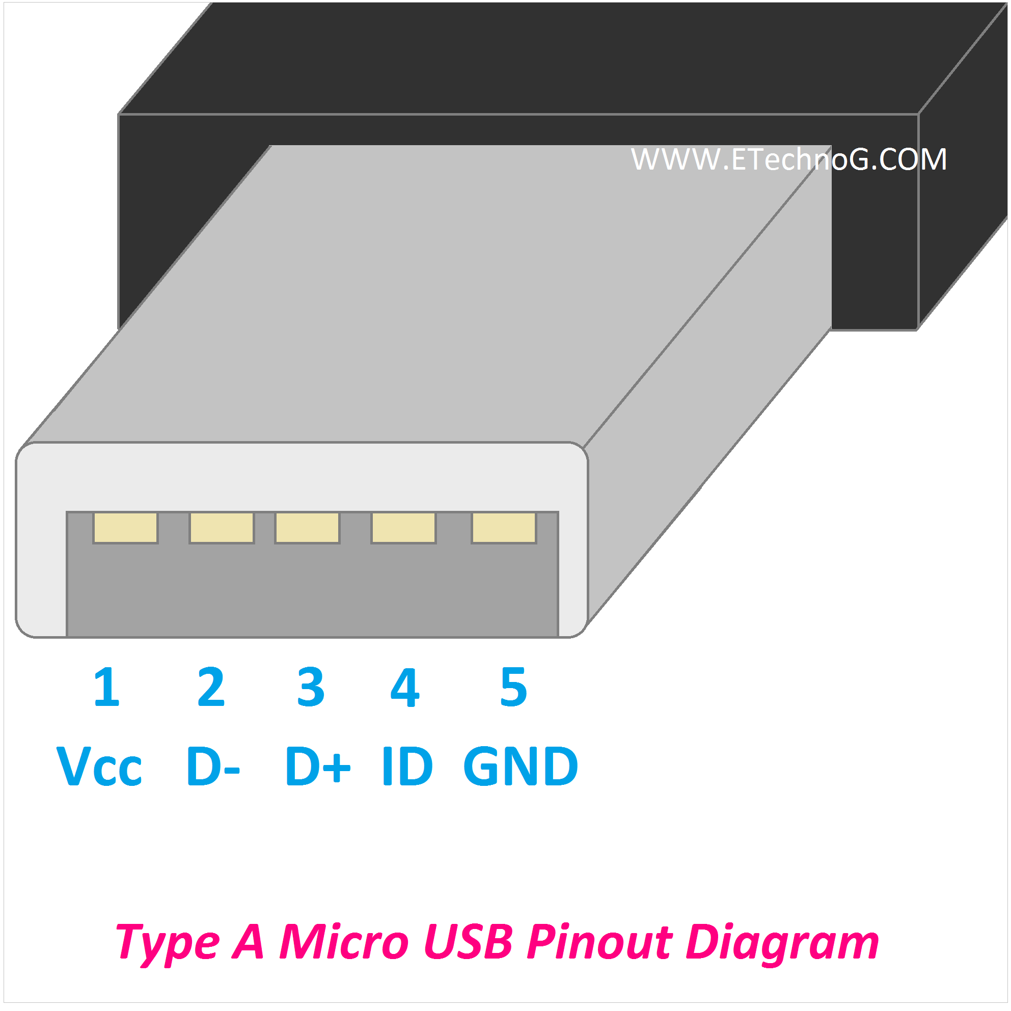
Here, you can see the pinout diagram of Micro USB Type A.
The Micro USB-A connector has a compact design with a rectangular shape and measures about 6.85mm by 1.8mm. It has a distinctive trapezoidal shape with a slanted top and bottom, which helps ensure proper orientation when plugging in the cable. The Micro USB-A has a total of five pins. These five pins are Vcc, D-, D+, ID, and Ground. Vcc and Ground are used to transmit electrical power. Generally, a 5V DC supply is transmitted. Data+(D+) or Data-(D-) are used to transmit data signals. ID is used for Mode Detect.
Type B Micro USB Pinout Diagram
Here, you can see the pinout diagram of Micro USB Type B.
Micro USB Type B connectors have a trapezoidal shape with a slanted top and bottom, similar to Micro USB Type-A connectors. They are designed to be plugged in a specific orientation to ensure proper connection. Micro USB Type B also has a total of five pins. Just the size and shape are different from type A. This type of connector is mostly used for the data transmission and charging of mobile phones and compact devices. It is also a very popular among the micro USB pins.
Micro USB Type C Pinout Diagram
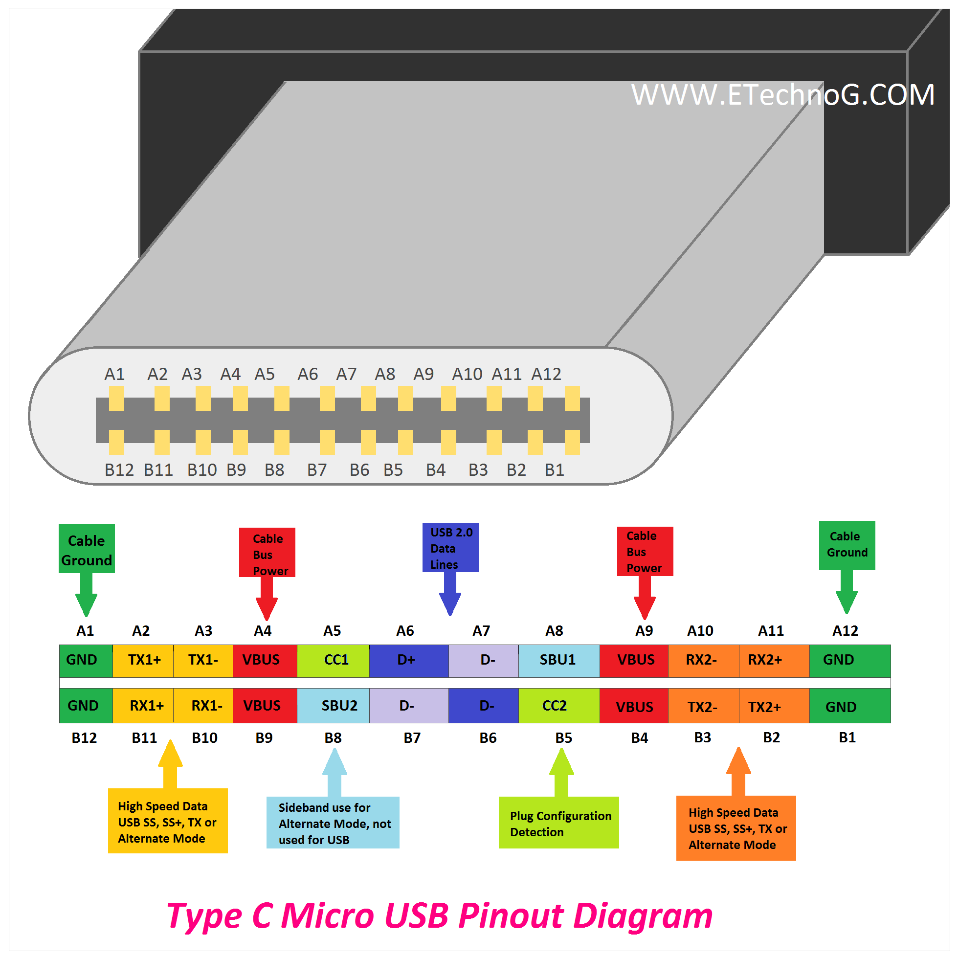
Here, you can see the pinout diagram of Micro USB Type C. It is mainly known as USB Type C rather than Micro USB.
Micro USB C is the latest connector used in all the latest devices. It has a total of 24 pins. USB Type-C is a small, oval-shaped connector that is reversible, which means it can be inserted into a device in either orientation. USB Type-C supports faster data transfer speeds, higher power delivery capabilities, and the ability to transmit audio and video signals. It is a versatile connector used in various devices, including smartphones, tablets, laptops, and peripherals. It helps to transfer high-speed data and power simultaneously. It has so many extra functions also.
See Also:


