RJ45 Pinout Diagram, Colour Code, Wiring Diagram(cat 6,7,5e)
Hey, in this article we are going to see the RJ45 Pinout Diagram and its terminal identification. Here, you can also see the RJ45 connector pin diagram and its connection for a crossover cable. RJ45 is an 8-pin connector that is used to connect computers and other networking devices to a Local Area Network(LAN). The full form of RJ45 is Registered Jack - 45. Actually, the RJ45 jack was originally designed for the telephone communication system but nowadays it is used for most of the networking communication systems.
RJ45 Pinout Diagram(T-568A)
Here you can see the pin diagram of RJ45 Jack.
When you identify the terminals of the RJ45 connector, hold the connector as the copper strips should towards your face. Now, identify serially 1 to 8 from the left side to the right side.
Here are the details of the RJ45 Colour Code,
Pin no.1 - White Green
Pin no.2 - Green
Pin no.3 - White Orange
Pin no.4 - Blue
Pin no.5 - White Blue
Pin no.6 - Orange
Pin no.7 - White Brown
Pin no.8 - Brown
Here is the table for the function of each pin.
| RJ 45 Pin | Color Codes | Function/Signal |
| 1 | White/Green | Data Transmit+ |
| 2 | Green | Data Transmit- |
| 3 | White/Orange | Data Receive+ |
| 4 | Blue | Unused |
| 5 | White/Blue | Unused |
| 6 | Orange | Data Receive- |
| 7 | White/Brown | Unused |
| 8 | Brown | Unused |
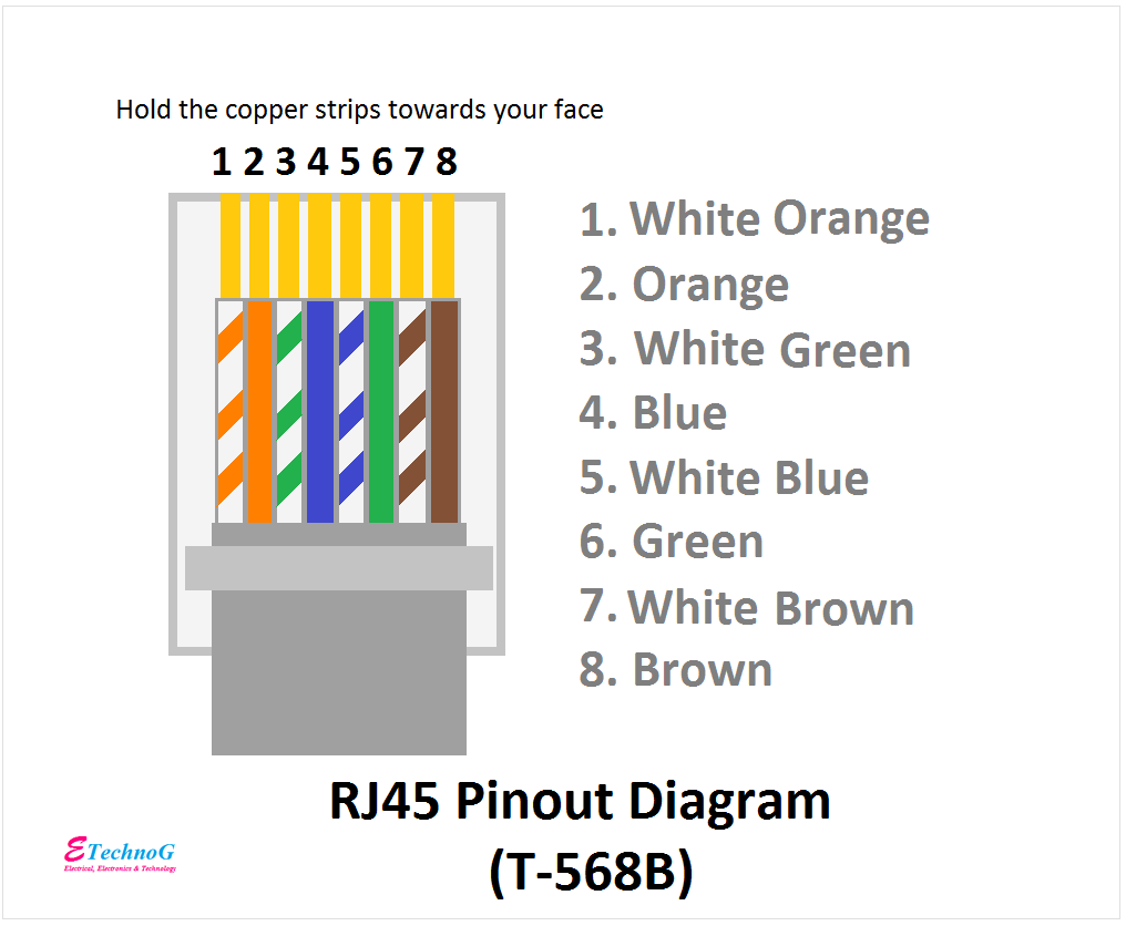
Pinout Diagram of RJ45(T- 568B)
Here you can see the pinout diagram and color code of the RJ45 Connector(T - 568B)
Here, also the same. Hold the jack as the copper strips should be towards your face. Then count 1 to 8 from left side to right side.
Here are the details of the color code,
Pin no.1 - White Orange
Pin no.2 - Orange
Pin no.3 - White Green
Pin no.4 - Blue
Pin no.5 - White Blue
Pin no.6 - Green
Pin no.7 - White Brown
Pin no.8 - Brown
Here is the table for the function of each pin,
| RJ 45 Pin | Color Codes | Function/Signal |
| 1 | White/Orange | Data Transmit+ |
| 2 | Orange | Data Transmit- |
| 3 | White/Green | Data Receive+ |
| 4 | Blue | Unused |
| 5 | White/Blue | Unused |
| 6 | Green | Data Receive- |
| 7 | White/Brown | Unused |
| 8 | Brown | Unused |
Read Also:
RJ45 Wiring Diagram for Cat 6, 7,5e
Connection and Wiring Diagram of RJ45 for Crossover Cable
A crossover cable is used to connect two network devices having different RJ45 connectors. Generally, a cross-over cable has both RJ45 Jacks, T-568A and T-568B it's both ends. Here, you can see the RJ45 wiring connection of a crossover cable.
For crossover cable connection at both ends, different connectors are connected. Here in the above diagram left side T-568A and the right side T-568B are connected. You can know the function and color codes from the below table.
| RJ 45 Pin | End 1 T-568A Color Codes | Function/Signal | End 2 T-568B Color Codes |
| 1 | White/Green | Data Transmit+ | White/Orange |
| 2 | Green | Data Transmit- | Orange |
| 3 | White/Orange | Data Receive+ | White/Green |
| 4 | Blue | Unused | Blue |
| 5 | White/Blue | Unused | White/Blue |
| 6 | Orange | Data Receive- | Green |
| 7 | White/Brown | Unused | White/Brown |
| 8 | Brown | Unused | Brown |
Read Also:


