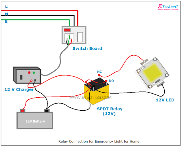
Relay Connection and Wiring Diagram for Emergency Light
Hey, we are going to see the Relay Connection and Wiring Diagram for the Emergency Light. You can make this circuit for your home. When power failure happens, the light will be automatically turned ON.
Let's see the Connection Diagram.
Connection of Relay for Emergency Light
Components Used
The components used in this circuit are,
1. 12V DC SPDT Relay
2. 12V LED
3. 12V Battery
4. 12 V Charger
Working Principle
When the main power supply is available, the coil of the relay remains energized. At this time, the battery will be charging. As the LED is connected to the NC terminal, it remains off condition.
When a Power failure occurs, or the main power supply is not available, the LED will be turned ON.
Here, 12V battery, 12V Relay, 12V Charger, and 12V LED are used. You can make the same circuit using a 24V Relay, 24V Charger, 24V LED, and two 12V batteries with the series connection.
Connection Procedure
1. First, find and identify the terminals of the Relay properly.
2. Connect the battery-positive terminal with the Relay Common Terminal.
3. Connect the Positive terminal of the LED to the Normally Closed or NC terminal of the Relay.
4. Connect the Charger output terminals across the Relay Coil.
5. Connect both negative terminals of the LED and Battery with the negative terminal of the Charger.
6. Again connect the battery charger positive terminal with the Normally Open or NO terminal of the Relay.
7. Give the power supply to the Battery Charger and it must be always connected to the main power supply.
Now your circuit is ready. Now, if a power failure occurs the LED will be turned ON.
Read Also:
- How to calculate the value of resistor for LED when connecting with Power Supply.
- Timer Switch Circuit Diagram for Light
- [Proper] 3 Way Switch Wiring and Connection Diagram
- Wiring Diagram for House with MCB Rating Selection Guide
- Wiring Diagram of Solar Panel with Battery, Inverter, Charge controller and Loads.
Thank you for visiting the website. keep visiting for more updates.

