Timer Switch Circuit Diagram for Light
Timer Switch Circuit
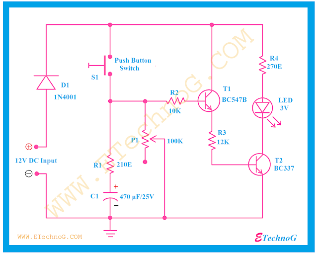
Here a simple circuit diagram of a Timer switch circuit is given. The required components are given below,
Components | Rating | Quantity | Indicated In the Circuit diagram |
PN Junction Diode | 1N4001 | 1 | D1 |
Push Button Switch | NO (Normally Open) switch | 1 | S1 |
Resistors | 210E | 1 | R1 |
Capacitor | 470 microfarad, 25V | 1 | C1 |
Potentiometer | 100K | 1 | P1 |
Resistor | 10K | 1 | R2 |
NPN Transistor | BC547 | 1 | T1 |
Resistor | 12K | 1 | R3 |
Resistor | 270E | 1 | R4 |
LED | 3V | 1 | |
NPN Transistor | BC337 | 1 | T2 |
Circuit Diagram:
When the push button switch is pressed the LED will be glow for a time duration. The glow time can be increased or decrease by the Potentiometer.
Read Also:
Thank you for visiting the website. keep visiting for more updates.

