IC 74138 Pin Diagram, Truth Table, Logical Circuit, Applications
IC 74138 is a Logical Decoder IC. It also has a demultiplexing facility. The IC 74138 is available in the market with the name of 74LS138. It is a 3 to 8-decoder IC. The internal circuit of this IC is made of a high-speed Schottky barrier diode.
IC 74138 Pin Diagram
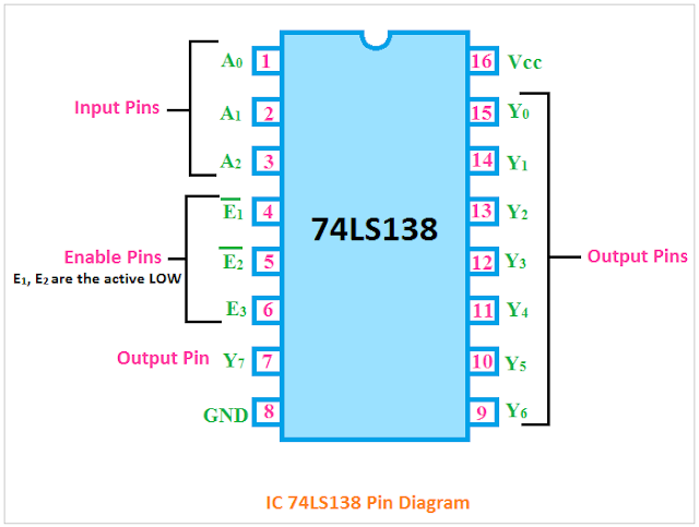
As you see in the below pin diagram, the IC 74LS138 has a total of sixteen pins.
1. The pin no. 8 and 16 are the ground and Vcc respectively for the power input.
2. There are a total of three input pins(pin no. 1, 2, 3). They are denoted by A0, A1, A2. So the IC 74LS138 can take three binary input signals.
3. There are three enable input pins E1, E2, E3(pin no. 4, 5, 6). E1 and E2 are the active LOW pins which means when low signals are applied to those pins they will be active.
4. Pins no. 7 and 9 to 15 are the output pins.
Logical Diagram of IC 74138
The logical circuit of the IC 74138 is made using NOT Gate, and AND Gates. You can see the circuit diagram in the below figure.
IC 74138 Truth Table
Here the truth table of IC 74138 is given below.
Operating Condition of IC SN74LS138
1. The supply voltage or Vcc should be given between 4.75V to 5.25V
2. The operating temperature range should be between 0 to 70-degree centigrade
Features of IC 74138
1. It is a very fast and high-speed IC.
2. It consumes very low power because it consists of low-power Schottky diodes.
3. It has a demultiplexing facility.
4. It has a very short propagation delay.
5. Appropriate Operating Temperature.
IC 74138 Applications
1. It is a decoder IC, the main application is to decode the digital signal.
2. They are used in digital memory circuits.
3. They are used in data routing applications.
4. They are used for demultiplexing of digital signals.
- 3 to 8 decoder circuit diagram. 3 to 8 decoder truth table.
- BCD to Seven Segment Display Decoder Circuit using IC 7447
- IC 7400 Pin Diagram, Circuit design, Datasheet, Application
- NOR Gate Truth Table, Internal Circuit Design, Symbol
- Pinout Diagram: IC 4013, IC 4014, IC 4015, IC 4016, IC 4018
- IC LM3916, LM3915, and LM3914 Pinout Diagram, Specification
Thank you for visiting the website. keep visiting for more updates.


