NOR Gate Truth Table, Internal Circuit Design, Symbol
NOR Gate
NOR gate is a logic gate that gives LOW output when any input signal is HIGH. The NOR gate can be said, it be the combination of the OR gate and NOT gate.
The NOR gate has a minimum of Two Inputs. First, it does the OR operation then it inverts the signal.
Let's know the NOR Gate Truth Table, Internal Circuit Design, and Symbol.
Symbol of NOR Gate:
Equivalent Circuit of NOR gate:
The NOR gate is the combination of OR gate and NOT gate which is shown below,
Operation of NOR Gate:
According to the truth table of the NOR gate below operations are,
1. When Input A and Input B both are LOW then the output of the NOR Gate will be HIGH.
2. When Input A is LOW and Input B is HIGH then the output of the NOR Gate will be LOW.
3. When Input A is HIGH and Input B is LOW then the output of the NOR Gate will be LOW.
4. When Input A and Input B both are HIGH then the output of the NOR Gate will be LOW.
Truth Table of NOR Gate:
Here A, B, and C denote the inputs of the NOR gate and the output is denoted by Q.
Truth Table of Two-Input NOR Gate:
A | B | Q |
0 | 0 | 1 |
0 | 1 | 0 |
1 | 0 | 0 |
1 | 1 | 0 |
Boolean Expression,

Truth Table of Three-Input NOR Gate:
A | B | C | Q |
0 | 0 | 0 | 1 |
0 | 0 | 1 | 0 |
0 | 1 | 0 | 0 |
0 | 1 | 1 | 0 |
1 | 0 | 0 | 0 |
1 | 0 | 1 | 0 |
1 | 1 | 0 | 0 |
1 | 1 | 1 | 0 |
Boolean Expression,

Internal Circuit Design of NOR Gate:
The internal circuit design of two-input NOR gate using Transistor is given below,
As you see in the above diagram, there are two transistors are connected. When both inputs are LOW(A=0, B=0), that means the BASE of both transistors not getting supplied so they cannot conduct current, therefore the current will flow through the load and the output will be HIGH.
When any one input is HIGH(A=0, B=1 or A=1, B=0), then one of them will be able to conduct current and it provides lower resistance than the load resistance so the current will flow through the Transistor and no current will flow through the load so the output will be LOW.
When both inputs are HIGH(A=1, B=1), then both transistors will conduct currents and no current will flow through the load so the output will be LOW.
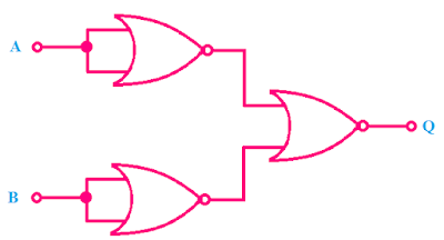
Design of Four Input NOR Gate using Two Input NOR Gates:
The boolean expression of Four Input NOR Gate is,

NOR Gate as Universal Gate:
NOR gate is also called Universal Gate. Using NOR gates we can design any other types of Logic gates.
OR Gate using NOR Gate,
NOT Gate using NOR Gate,
AND Gate using NOR Gate,
Examples of NOR Gate ICs:
1. Quad 2 input NOR gate: IC7402
2. Tripple 3 input NOR gate: IC7427
3. Dual 4 input NOR gate: IC74260
Read Also:
- NOT Gate Truth Table, Internal Circuit Design, Symbol
- [BEST] Application and Uses of Logic Gates with Practical Examples
- Types of Multiplexer Applications, Uses, Circuit and Truth Table
- AND Gate Truth Table, Internal Circuit Design
- OR Gate Internal Circuit Design, Truth Table
- NAND Gate Truth Table, Internal Circuit Design
Thank you for visiting the website. keep visiting for more updates.


