4-Pin, 5-Pin Automotive Relay Pinout and Wiring Diagram
Hey, in this article, we are going to see 4-Pin and 5-Pin Automotive Relays Pinout Diagram, Wiring Diagram, and Connection Procedures. Automotive relays are commonly used in vehicles to control various electrical circuits, such as headlights controlling, horns controlling, fans controlling, and many more. The main difference between a 4-pin and 5-pin automotive relay is the number of pins and their functions. As their name suggests, the 4-Pin Relay has four pins whereas a 5-Pin Relay has five Pins. If we see the difference in pin numbers the 5-pin relay has an additional terminal which is identified as 87A.
Pinout Diagram and Terminal Identification
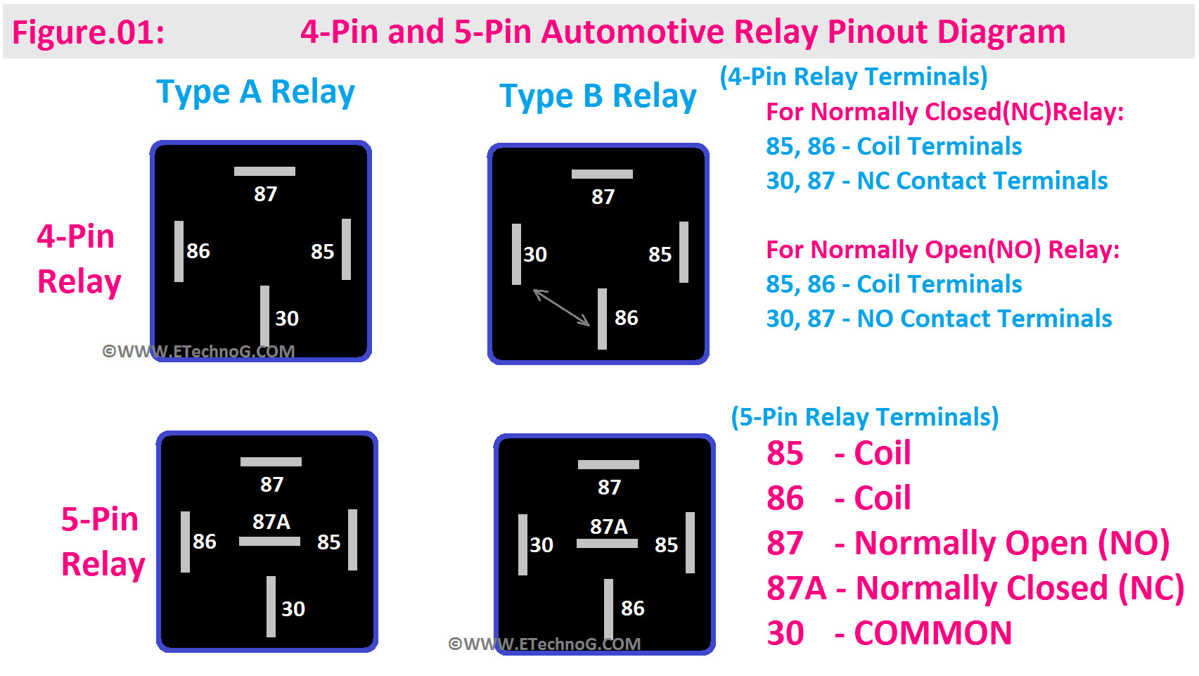
Here, in the below figure, you can see the Pinout Diagram of both 4-Pin and 5-Pin Relays.
4-Pin Relay Pinout
The 4-Pin Relay has the following Pins,
30 (Common): This pin is the common connection for the switch and the load. It carries the primary current when the relay is activated.
85 (Coil Terminal): This pin is used to provide the coil with a ground (negative) signal to activate the relay. Applying a ground to this pin energizes the coil and closes the switch contacts.
86 (Coil Terminal): This pin is used to provide a positive (usually 12V) signal to the coil. When a positive voltage is applied to this pin along with the ground on pin 85, the coil is energized, closing the switch contacts.
87 (Normally Open or Normally Closed): For Normally Open(NO) Relays, this pin is disconnected from the common (pin 30) when the relay is not activated. When the relay is activated it makes a closed contact with the common terminal. On the other hand, For Normally Closed(NC) Relays, this pin is connected to the common (pin 30) when the relay is not activated. When the relay is activated it makes an open contact or disconnects from the common terminal
5-Pin Relay Pinout
The 4-Pin Relay has the following Pins,
30 (Common): Same as in the 4-pin relay, it is the common connection for the switch and the load, carrying the primary current when the relay is activated.
85 (Coil Terminal): This pin is used to provide the coil with a ground (negative) signal to activate the relay, just like in the 4-pin relay.
86 (Coil Terminal): This pin is used to provide a positive (usually 12V) signal to the coil, again, similar to the 4-pin relay.
87a (Normally Closed): This pin is connected to the common (pin 30) when the relay is NOT activated. It provides an alternate path for current when the relay is not energized.
87 (Normally Open): This pin is connected to the common (pin 30) when the relay is activated. It provides the output to the load when the relay is closed.
**Also, remember that there are two types of Relay - Type A and Type B. This classification is based on the position of the Pin 30 and 86. See the above diagram carefully for a better understanding**
4-Pin Relay Wiring Diagram
Here, in the below wiring diagram, you can see we have used a NO type 4-Pin Relay to control a Light.
Here, you can see we have connected the coil pins to a battery in series with an SPST switch. The light is also connected to the battery through the relay NO contact terminals. So, when we turn on the SPST switch the relay will make its NO contact into NC so the light will turn. When we turn off the switch the light also be turned off.
5-Pin Relay Wiring Diagram
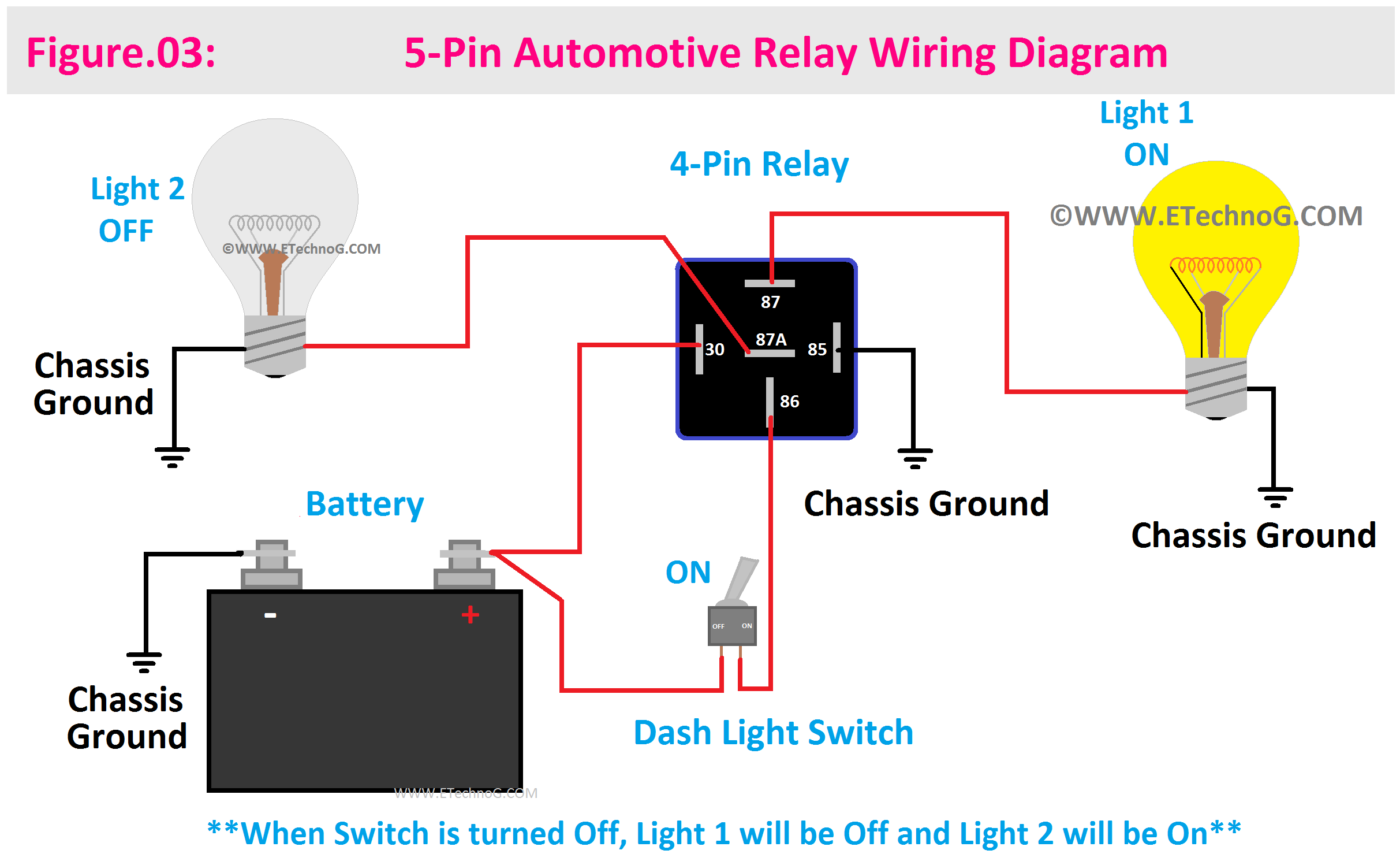
Here, in the below wiring diagram, you can see we have used a 5-pin Relay to control two different lights.
You can see, we have connected one light to 87 Pin(NO terminal) and one light to 87A Pin (NC terminal). So when the relay is not activated, the light connected to the 87A pin will glow and when the relay is activated, the light connected to the 87 pin will glow.
Read Also:
- Car Sound System Wiring Diagram(Speaker, Amplifier, Receiver)
- Fog Light Wiring and Connection Diagram with Relay and Switch
- Ignition Switch Wiring Diagram and Connection for Pins
- Trailer Wiring Diagram - 4, 5, 6, 7 Pin/Wire (with Brakes, Lights)
- Three-Phase Inbuilt Regulator Alternator Wiring Diagram in Car
- Car Starter Solenoid Wiring and Connection Diagram Explained


