Single Phase Motor or Pump Connection with Timer
Here, in this article, we are going to see the connection diagram between a Single Phase Motor or Pump and a Digital Programmable Timer. This type of arrangement is used in various applications where controlled or timed operation is necessary. For example, In industrial sectors single-phase motors and pumps may be used for tasks like the operation of conveyor belts, mixers, or ventilation systems. Timers can be used in the control system to automate these processes, reducing manual intervention.
Even not only industrial settings, domestic applications such as household applications also use this motor and timer combination. This arrangement is also used in applications where a tank or container needs to be filled to a specific level, a timer can control the pump's operation to prevent overfilling. This is common in water storage tanks, swimming pools, and chemical dosing systems.
Connection Diagram
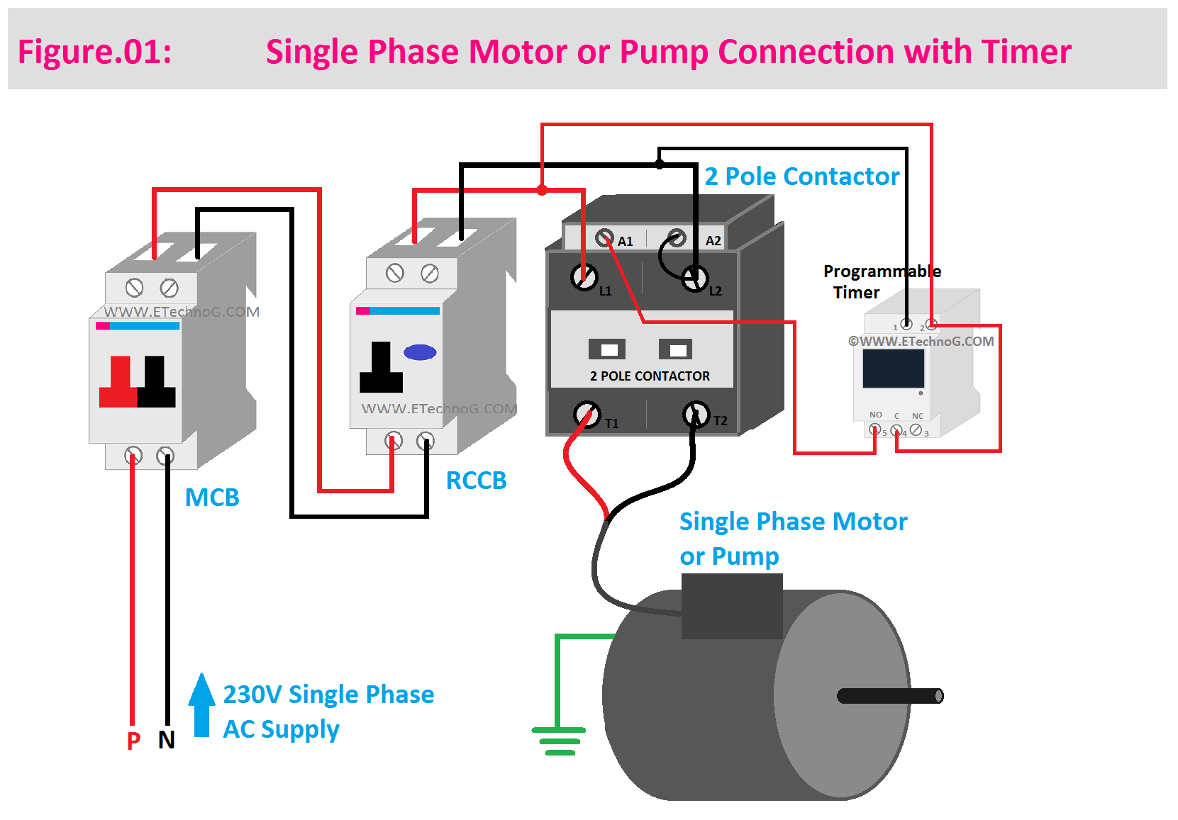
Here, you can see the connection diagram between a single-phase motor or Pump and a Digital Programmable Timer with some additional devices such as MCB, RCCB, Contactor, etc.
Components Used
- A 2-Pole MCB - As the main breaker
- A single-phase RCCB - for leakage protection
- A 2-Pole Contactor with 230V AC Coil Supply
- A Programmable Digital Timer
- Motor or Pump
Wiring Procedure
- The single-phase main input power supply is to be connected to the input of the 2-Pole MCB.
- Connect the Output of the MCB to the Input of the RCCB by maintaining proper phase and neutral connection.
- Now, connect the output of the RCCB to the main input terminals of the Contactor.
- Connect the output of the contactor to the motor or pump.
- Now, connect the neutral terminal of the contactor coil to the neutral terminal of the input power terminal of the contactor.
- Connect the Phase terminal of the contactor coil to the NO terminal of the Timer.
- Connect the input power terminals of the Timer to the output of the RCCB.
- Connect the Common terminal of the Timer to the phase terminal of the input power source.
Operation Procedure
- First, of all turn on the MCB.
- Then Turn On RCCB.
- Now Program your Timer or set the timing according to your On/Off operation timing interval.
- Once you set the timing in your timer the motor or pump will automatically turn On and turn Off.
Remember that this system does not have any extra switches for manual on/off the motor. If the timer has any button for manual on/off then only you can on/off the motor manually.
Working Principle
Here, the MCB is used to protect the circuit from Overload and Short Circuit Faults. If the motor draws over current or any short circuit fault happens within the Circuit, the MCB will trip and disconnect the power supply.
Here, the RCCB is used to give protection against ground fault, leakage current fault, and electric shock. When there is any unwanted current flow from the phase terminal to any other path instead of neutral the RCCB will trip and disconnect the power supply.
You can see the motor is connected through the Contactor. So, when the coil of the contactor is energized the contactor will close its contacts, the motor will get the power supply and it will start running.
You can see the contactor coil is connected to the power supply through the Timer NO contacts. According to the set timings, the Timer changes its NO contact into NC contact so the contactor coil gets the power supply. Once the contactor coil gets the power supply, the contactor will close its main contacts and the motor will start running. Thus the timer can control the motor automatically.
Read Also:

