6-Pin Relay Pinout and Wiring Diagram
Here, in this article, we are going to see the 6-Pin Relay Pinout and Wiring Diagram. As its name suggests, the 6-Pin relay has six pins. A normal SPST relay has a total of 5 pins - two pins for coil, one pin for common, one pin for NO, and one pin for NC. The 6-pin relay has an additional pin to provide additional functionality or special uses. In some, 6-pin relays the additional pin is used for an additional NO pin or additional NC pin, or additional common terminal(as shown in the below figure). Even in some 6-pin relays that additional oin is used if the relay has a dual coil.
6-Pin Relay Pinout Diagram
Here, you can see in the below pinout diagram, the 6-pin relay that has an extra common terminal.
Here are the details of each pin,
Coil Terminals: Pin no. 2 and pin no. 5 of the relay are the coil terminals. They may be identified as Coil + and Coil-. When voltage is applied across the Coil+ and Coil- pins, it energizes the coil and activates the relay.
Common (COM): Pin no.3 is the common terminal of the relay which is also known as the common contact. It is connected internally to either the Normally Open (NO) or Normally Closed (NC) contact, depending on the state of the relay.
Normally Open (NO): Pin no. 1 is the NO terminal which is one of the output terminals. When the relay is not energized (deactivated), there is no electrical connection between the Common (COM) and Normally Open (NO) pins. When the relay is energized (activated), the Common (COM) and Normally Open (NO) pins make electrical contact.
Normally Closed (NC): Pin no. 6 is the NC terminal which is another output terminal. When the relay is not energized (deactivated), there is an electrical connection between the Common (COM) and Normally Closed (NC) pins. When the relay is energized (activated), the electrical connection between these two pins is broken.
Extra NO or NC or Common: Here, the 6-pin relay has a second common terminal that is pin no.4. Some 6-pin relays may have a second Normally Open (NO) or Normally Closed(NC) contact instead of a second common contact. In this case, the pinout would be the same as mentioned above, but with a second Normally Open (NO) or Normally Closed(NC) contact instead of a second common.
6-Pin Relay Wiring Diagram
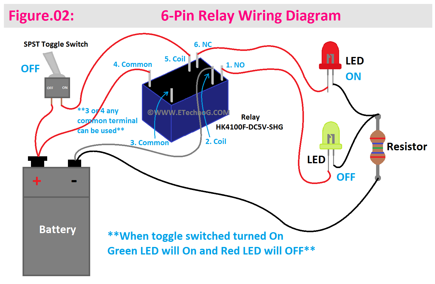
Here in the below wiring diagram, you can see we have used a 6-pin relay to control two different lights.
As we know pins 3 and 4 are both common terminals so we can use any one of them(here we have used pin no. 4). The red LED is connected to the NC terminal and the Green LED is connected to the NO terminal. So when the relay is not activated, the Red LED will glow but when the relay is activated, the Green LED will glow and the Red LED will be turned off.
6-Pin relay with an extra common terminal provides you so many advantages for some specific applications. You can use one common terminal for one function and the other common terminal for a different function. This versatility can be valuable in applications where you need to switch between two different devices or modes of operation.
For example, a 6-pin relay with an extra common can be used in motor control applications to reverse the direction of rotation of a motor. By connecting one common terminal to one set of contacts for forward motion and the other common terminal to a different set of contacts for reverse motion, you can control the motor's direction.
Read Also:


