Simple Touch Sensor Switching Circuit using IC 555
Here, in this article, we are going to build a simple touch sensor switching circuit using IC 555. A touch sensor switching circuit is a common electronic circuit that can turn on or off a device, such as an LED or a relay when a person touches a sensor. This type of circuit is often used in various applications like touch-sensitive lamps, proximity switches, and interactive projects. Basically, here we build this circuit to turn On a LED bulb when a person the touch sensor. But you can use any other device instead of this LED bulb whatever you want to control.
The Touch Sensor is basically a piece of conductive material like a wire, foil, or touch sensor module. The touch sensor is a piece of conductive material (like a wire) that is not connected to anything. When a person touches the sensor, their body capacitively couples with the sensor, creating a tiny current flow. And this current flow activates the circuit to do the further operation.
Circuit Diagram
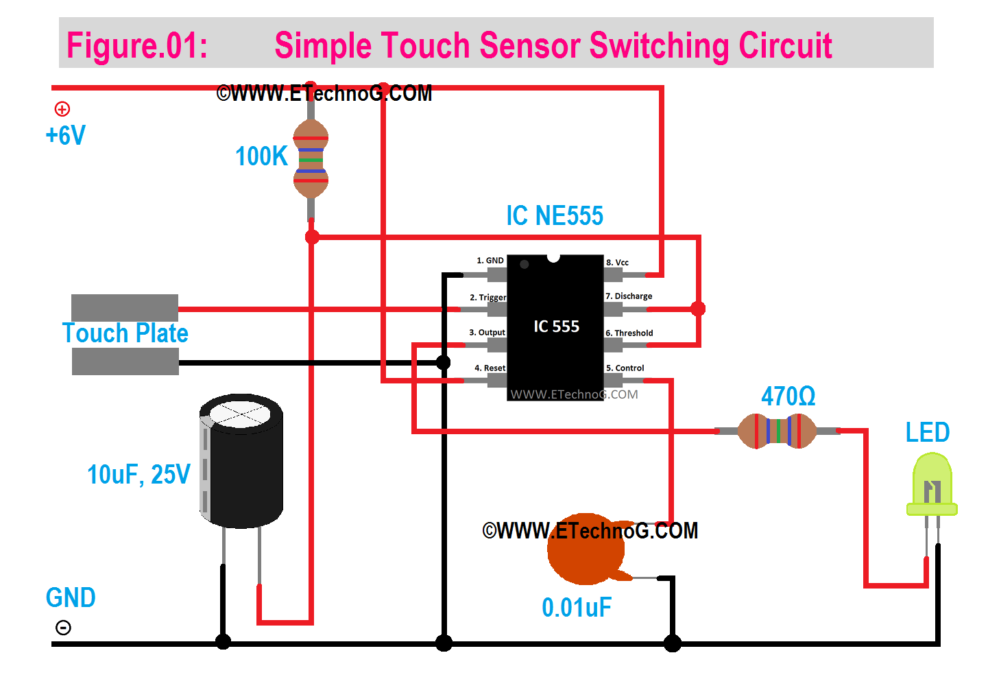
Here, you can see the diagram of a Simple Touch Sensor Switching Circuit using IC 555.
List of Components
- IC NE555 - 1 PCs
- Touch Sensor (e.g., a piece of conductive material like a wire, plates, foil, or touch sensor module)
- 100 Kilo-Ohm Resistor
- 470 Ohm Resistor
- LED
- 10uF, 25V Electrolytic Capacitor
- 0.01uF Ceramic Capacitor
- 6V DC Power Supply
Connection Procedure
- Connect the Vcc(pin 8) and Reset(pin 4) terminals of the IC 555 to the positive terminal of the power source.
- Connect the 100K resistor and the 10uF capacitor in series across the power source. And connect the middle joint of that capacitor and resistor to pins 6 and 7 of the IC 555.
- Connect pin 5 of the IC 555 to the negative terminal of the power source in series with a 0.01 uF ceramic capacitor.
- Connect pin 3(output terminal) of the IC 555 to the positive terminal of the LED and connect the negative terminal of the LED to the negative terminal of the power source.
- Connect the Ground terminal(pin 1) of the IC 555 to the negative terminal of the power source.
- Connect the trigger terminal(pin 2) of the IC 555 to any one terminal of the touch sensor.
- Connect another terminal of IC 555 to the negative terminal of the power source or the ground terminal of the IC.
Operation
When nobody touches the sensor, the circuit will not be triggered and the LED will be in Off condition. But when a person touches the sensor the circuit will trigger and the LED will turn On for a few seconds. We can use a relay to connect any other high-capacity load or lighting or any system instead of this LED.
In this touch sensor circuit, when a person touches the sensor, their body's capacitance causes a change in the electrical conditions of the circuit. This change is detected and processed by the components, causing the LED to turn on. The resistors, capacitors, and NE555 timer contribute to creating the required control signal and ensuring stable operation of the circuit.
Read Also:

