Simple Overload and Short Circuit Protection Circuit Diagram
Hey, in this article, we are going to see the circuit diagram for a simple homemade Overload Protection and Short Circuit Protection system. You can use this circuit with a 6V DC or 12V DC power supply. This circuit is best suitable for use with batteries. Overload and Short circuits can result in overheating, venting, sparks, explosions, or fires of the batteries. So this circuit will work as a safeguard for your batteries.
Basically, we have built this circuit using a Relay with some components. Overload and short circuit protection circuits using relays can be used in various applications to ensure the safety and proper functioning of electrical systems.
For example, in vehicles, these circuits can be used to protect various electrical components, such as headlights, windshield wipers, and power windows, from overload or short-circuit conditions. This prevents damage to both the vehicle's electrical system and the components themselves.
For small solar power systems or off-grid setups, where 6V to 12V batteries are commonly used, protection circuits with relays can prevent damage due to overload or short circuit events caused by varying sunlight conditions or system malfunctions. Devices such as audio amplifiers, small motors, and lighting systems that operate within the 6V to 12V range can benefit from these protection circuits.
A Simple Short Circuit Protection Circuit Diagram
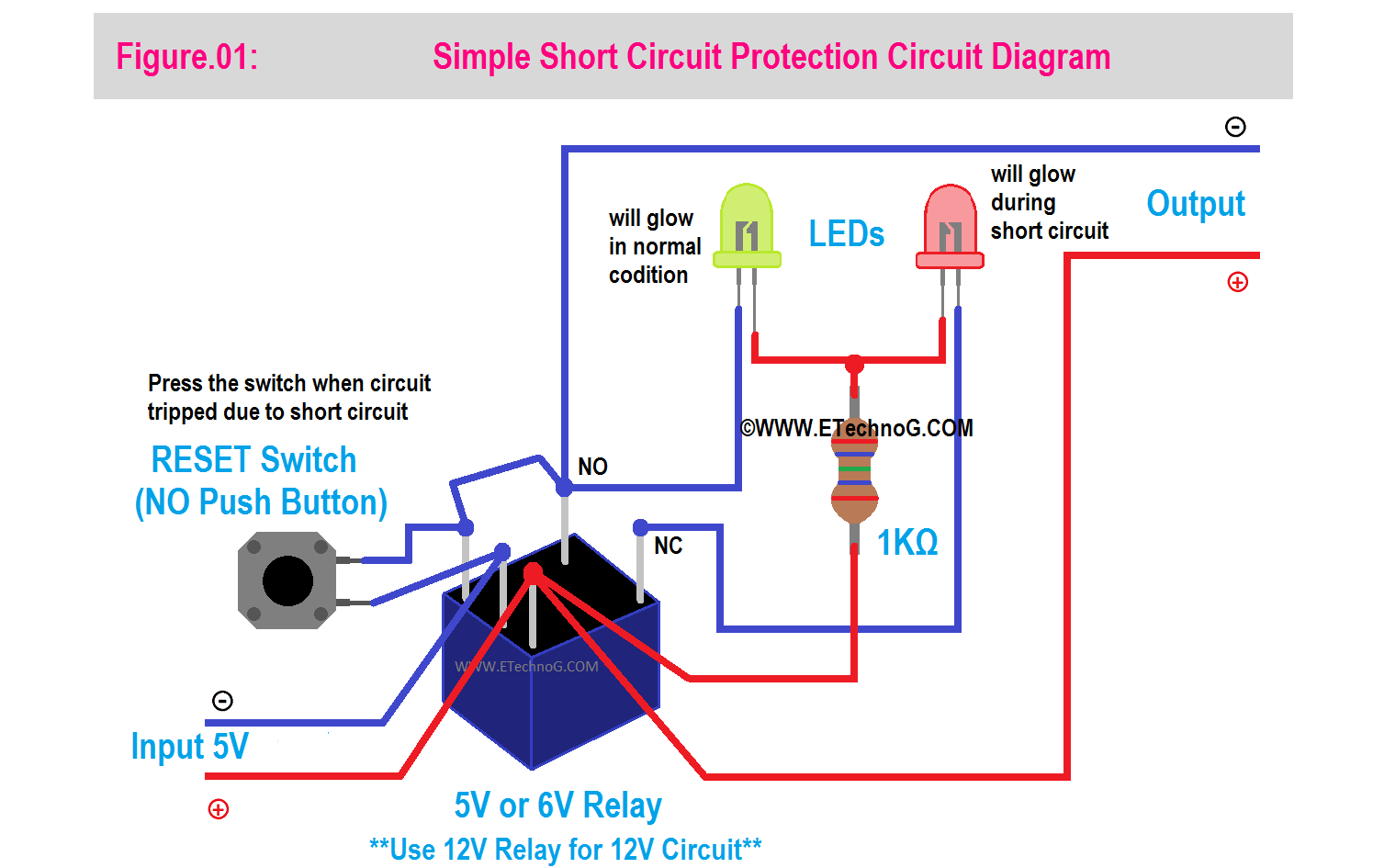
Here, you can see the circuit diagram for a simple Short Circuit Protection system using Relay.
Component List
- A 5V or 6V DC Relay(if you use 6V power source) or A 12V DC Relay(if you use 12V power source)
- One Red Color LED and a Green Color LED
- One NO(Normally Open) Push Button Switch
- One 1 Kilo-ohm Resistor
Connection Procedure
- The positive terminal of the power source is to be connected to the coil 2 terminal of the relay coil and the same is used as the positive output terminal.
- The negative terminal of the power source is to be connected to the common terminal of the relay.
- The push button switch should be connected between the common terminal and the coil 1 terminal of the Relay Coil
- Also, connect this coil 1 terminal to the NO terminal.
- Now connect the positive terminal of both LEDs and finally connect to the positive terminal of the power source or the coil 2 terminal of the relay in series with a 1 Kilo-ohm resistor.
- Connect the negative terminal of the Green LED to the NO terminal and Connect the negative terminal of the Red LED to the NC terminal.
- Also, use the NC terminal as the negative output terminal.
Operation and Working Principle
First of all, connect the load to the output terminals. Now, when you connect the power source to the input the Red LED will glow and the load will not get any power supply. In this case, you have to press the Reset Switch. Once you press the Reset Switch the green LED will turn On and the load will get the power supply. Now, if there is any short circuit happening at the output or load side the Red Light will be turned ON and the load will be disconnected from the power supply. After removing the short circuit, again you need to press the Reset switch to work the circuit again.
The working principle of this circuit is very simple. Actually, the relay coil is connected in series between the power source and load. So when the short circuit fault occurs, a high current flow through the relay coil, and it gets energized. Once the relay coil energies it changes its contacts that interrupt the current flow between the power source and the load. Thus the power source got protected from the short circuit fault.
Read Also:
Adjustable Overload Fault and Short Circuit Protection Circuit Diagram
Here, you can see the circuit diagram of an Overload Fault and Short Circuit Protection system.
The above circuit diagram is the same as the old circuit, just the difference is here we have used a potentiometer and a transistor between the Coil and NO terminals.
Additional Component Used
- One BC547 Transistor
- One 100K Potentiometer.
Connection Procedure
- The Connection procedure is the same as explained above. Here, we just need to know how to connect the potentiometer and the transistor.
- In the above connection procedure, we have shorted coil 1 and NO terminal. But here we do not short those terminals directly.
- Both side terminals of the potentiometer are to be conceded two the coil 1 and NO terminal.
- The Emitter terminal of the Transistor is to be connected to the NO terminal, the Collector terminal is to be connected to the Coil 1 Terminal, and the Base terminal is to be connected to the middle terminal of the Potentiometer.
Operation
You can set or adjust the overload current by rotating the potentiometer. Rest all the working procedure is same as above explained.
Read Also:


