Photodiode Symbol, Diagram, Circuit, Characteristics
Basically, a photodiode is a semiconductor device that has almost the same construction as a PN Junction Diode. The main function of a photodiode is to allow current through it or produce current itself when light falls on its junction. Photodiodes are designed with a window made of fiber optic or transparent material, so light can easily reach its junction. In the below diagram of the phototransistor, you can see, how a conventional photodiode looks. You can see at the top, a transparent window type available.
Photodiode Diagram
When a light focused on a photodiode, it absorbs photons from the light. These photons cause to create electron-hole pairs in the photodiode. The holes move towards the Anode, electrons towards the cathode, and a photocurrent is produced.
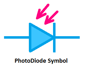
PhotoDiode Symbol
Here, you can see the symbol of photodiode.
You can see it almost the same as the Light Emitting Diode or LED. Just the difference is, the arrows are towards the diode symbol which indicates that when light falls on it, it will work.
PhotoDiode Characteristics
A photodiode work in two different modes,
- Photovoltaic Mode
- Photoconductive Mode
In the photovoltaic mode, the photodiode generates electric current and voltage when it put in the light. The total current generated by a photodiode is the sum of Dark Current(the current generated in absence of light) and photocurrent(Current generated in the presence of light). The photodiode having a low dark current will have high sensitivity. In photovoltaic mode, the current will flow from the anode to the cathode when the terminal of the photodiode is short-circuited. So, in the photovoltaic mode, the Photodiode act as a power generating device. Also, note that in the photovoltaic mode, the photodiode does not need any external power supply for its operation, even it generate power itself.
Here you can see the reverse current illumination curve below. Here the reverse current(IR) is shown in the verticle axis and the illumination(E) is shown in the horizontal axis. The reverse current is measured in mA and the illumination is measured in mW/cm2. Also, you can see, the reverse current increases with the increase of illumination level.
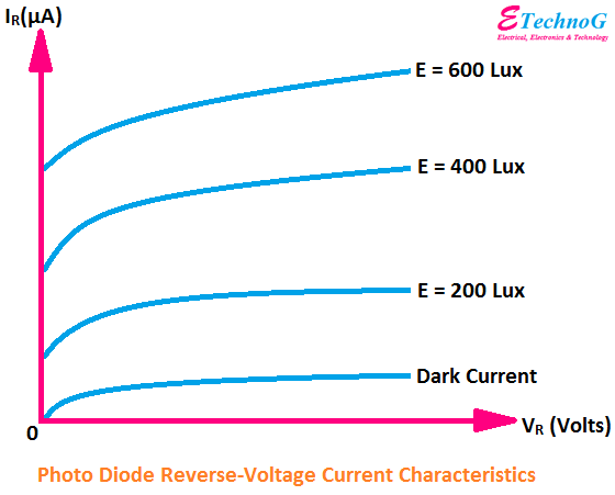
To operate a photodiode in the photoconductive mode, it should be connected in the reverse bias. In the photoconductive mode, a photodiode allows the current to flow through it when light falls on it. When there is no light, no current will flow except the dark current. Photoconductors are used in photoconductive mode when they are used in electronic sensing circuits with an external power supply. The current generated by a photodiode is very low, so it can not drive an electronic circuit. For this reason, an external power supply is used. So, we can say that in the photoconductive mode, the photodiode is act as a Switching device.
Here, you can see the reverse voltage-current curve of the photodiode at different illumination levels. Here the reverse current is shown in the vertical axis and the reverse voltage is shown in the horizontal axis.
Photodiode Circuit Diagram
Here you can see the circuit diagram of Photodiode below.
The working principle of this circuit is very simple. It is a light-sensing circuit. When the photodiode detects any light it will produce a voltage. Here the OpAmp is used as a comparator. The OpAmp will compare the voltage produce by the photodiode with the reference voltage supplied by the Vcc or main power supply. According to it, it will give the output. Here, an LED is connected to the output of the circuit. So, when the circuit senses a light, the LED will be glow and when there is no light the LED will be in the Off condition.
This circuit can be used as a automatic light on/off light. We can use a high voltage light by connecting a relay.


