Float Switch Connection Diagram and Wiring with Water Pump
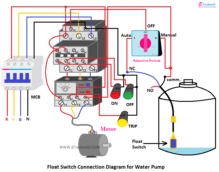
In this article, we are going to see the Float Switch Connection Diagram and wiring. This circuit can be used to fill a water tank automatically. Float Switch is basically is the combination of NO and NC circuit that changes its contacts depending upon the alignment at which it is placed. In the connection of the float switch, we have used the below apparatus,
- Three Pole Contactor
- Thermal Overload Relay
- Four Pole MCB
- Selective Switch
- 230V Float switch
- Three Indication lamps
Float Switch
The float switch used in this circuit has a total of three terminals. The black color wire is common, the Blue color wire is NC(Normally Closed), and the Red Color wire is NO(Normally Open). When the float switch is aligned from top to bottom as shown in the below figure, the Blue is NC and the Red is NO. But when the float switch is aligned from bottom to top then the Blue becomes NO and Red becomes NC. So generally, for the water filling purpose float switch is connected with the common and NC terminal. So in normal conditions, the motor will be On, and when the water gets filled in the tank the motor will be turned off.
Float Switch Connection Diagram
Let's see the connection diagram of Float Switch.
Here you can see we can manually turn on the motor or we can run in auto mode. When the selective switch is positioned to manual mode the contactor will turn on and the motor also be turned on and it will run until we manually turn it off. When we rotate the knob of the selective switch to position 1 or auto mode the motor will turn on when the water level goes low. Once the water is filled, the motor will be turned off automatically.
Connection Procedure
1. Connect the four pole MCB as input control as shown in the above figure.
2. Connect all three phases to the input of the contactor. Connect the motor terminals to the output of the thermal overload relay as shown in the above figure.
3. Connect the A1 terminal of the contactor with terminal '1' of the selective switch.
4. Connect the A2 terminal of the selective switch with the 'R' Phase through the NC contacts of the OLR as shown in the above figure.
5. Connect the common terminal of the Float switch with the A2 terminal of the selective switch and the NC terminal of the float switch with the A1 terminal of the selective switch.
6. Connect the Red color indication lamp to the 'R' phase through the NO contacts of the contactor as shown in the above figure. So when the contactor turns On the red color lamp also be turned on.
7. Connect the green color indication lamp to the 'R' phase through the NC contacts of the contactor as shown in the above figure.
8. Connect the yellow color indication lamp through the NO contacts of the Thermal overload relay as shown in the above figure.
Read also:
- Proper UPS Connection with Loads, Inverter, Computer at Home
- Portable Generator Connection Diagram with Home Power Supply
- Stabilizer Connection Diagram and Wiring for Home
- Inverter connection diagram. Install Inverter and Battery at Home.
- [Proper] Ceiling Fan Connection with Regulator, Switch and Capacitor

