Different Types of Parallel Circuit Diagrams Explained(AC, DC)
Parallel circuits are those where all the components are connected in parallel to each other. Some common examples of parallel circuits are all the loads in our houses are connected in parallel, LC tank Circuits, Audio Distribution circuits, etc. Parallel circuits have different properties than series circuits. So, learning about parallel circuits is also very important.
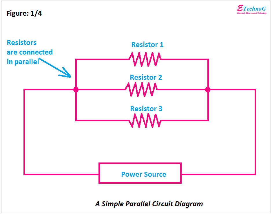
A simple Parallel Circuit Diagram
Here, you can see a very simple parallel circuit where three resistors are connected in parallel. If we consider both ends of a resistor as end 1 and end 2 then end 1 of all the resistors are connected together and end 2 of all the resistors are connected together. Thus a parallel circuit is built. In a parallel circuit, the power source and load both are connected in parallel.
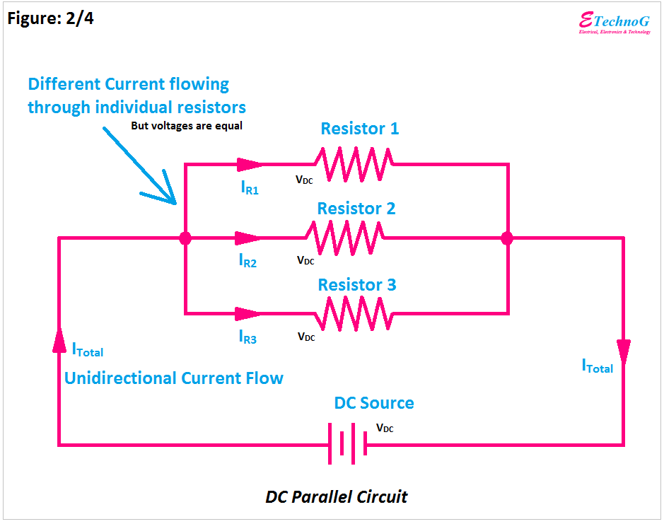
DC Parallel Circuit
Here, you can see the diagram of a DC parallel circuit. Here, three resistors are connected in parallel and the circuit is powered by a DC source.
The main characteristics of a DC Parallel Circuit are,
- The current flows through individual components are different. It depends upon their internal resistance.
- The voltage across each element is the same or equal.
- As it is powered by a DC source, so the current flow in the whole circuit will be unidirectional.
- There is no impedance occurs in the circuit.
- Damaging any one component does not affect the other components of the circuit.
AC Parallel Circuit
Here, you can see the diagram of an AC Parallel Circuit. Here also, all the components are connected in parallel, and the circuit is powered by an AC power source.
The main characteristics of an AC parallel circuit are,
- The voltage across each component is the same.
- Current flowing through individual components are different.
- The current flowing through the whole circuit is bidirectional.
- There will be impedance if the circuit consists of reactive elements.
- In an AC circuit, the power factor also is taken for the calculation.
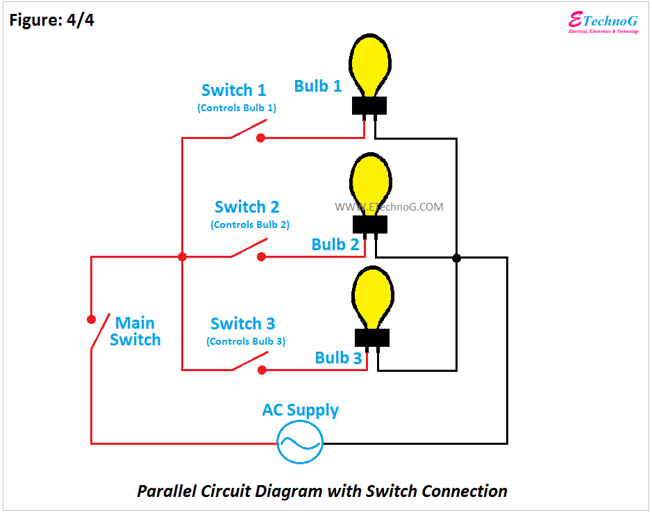
Parallel Circuit with Switch Connection
Here, you can see a parallel circuit consisting of three lights. Each light has its own individual switch and a main switch. The individual switch gives you control of the individual bulbs separately. And the master switch is connected just after the power supply so it can turn off or turn on the power supply for the whole circuit.
As per the above circuit when you turn off the main switch all of the lights will be turned on even if their individual switches are turned on. As you can see switch 1 controls light 1, switch 2 controls light 2, and switch 3 controls light 3.
There are so many advantages of a parallel circuit over a series circuit such as,
- The low voltage is required to control the same number of loads over a series circuit.
- Breaking or opening the circuit in any one load can not affect the other loads.
- In most of the cases, loads connected in a parallel circuit can operate at their maximum capacity as they do not depend on the other loads.
- All the lights will glow the same if they have the same rating and are connected in a parallel circuit.
Read Also:


