Different Types of Series Circuit Diagrams Explained(AC, DC)
Series circuits are those where the components are connected end to end or in a series combination. Some common examples of series circuits are a simple light and switch connection, Christmas lights, etc. The concept of a series circuit is very essential to understand.
A simple Series Circuit Diagram
Here, you can see three resistors are connected in series. If we consider a resistor has two ends - the first end and the second end. So the second end of the first resistor is connected to the first end of the second resistor. In that way, all the resistors are connected. Here, we have just taken an example with some resistors but actually, all the series circuits have all the components in that way.
DC Series Circuit
Here, you can see the diagram of a DC series circuit, where all the components(resistors) are connected in series and powered by a DC Supply.
The main characteristics of a DC series circuit are,
- The current Flow through each component is the same or equal.
- But voltage across the individual resistors is different.
- The flow of current through all the components is unidirectional.
- There is no impedance occurs in the circuit.
- In a series circuit damage of any one component can affect all the components connected to the same circuit.
AC Series Circuit
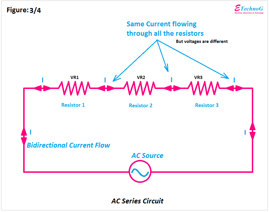
Here, you can see the diagram of the AC Series circuit. Here also, all the components are connected in series but the circuit is powered by an AC source.
The main characteristics of the AC Series Circuit are,
- The current flowing through each component is the same.
- The voltage across individual components is different.
- The flow of current through each component is bidirectional as it is powered by an alternating current source.
- Impedance occurs in the AC series circuit that opposes the flow of current so the overall current flow decreases as compared to the DC circuit.
Series Circuit Diagram with a Switch Connection
Here, we have shown a series circuit that consisting three lights connected in series. And a switch is also connected in series just after the power source.
Here, the switch is connected before all the lights but remember that the switch will provide the same operation and function if you connect it anywhere in the circuit in series. Also, note that here you cannot control the lights individually. Whenever you turn off the switch all the lights will be turned off and vice versa. So this is a drawback of a series circuit.
The other important drawbacks are,
- The voltage across each component will decrease when a new component is added.
- More voltage is required to control the same number of loads as compared to the parallel circuit.
- All the lights will not glow the same if they have the same rating and connect in a series circuit.
- Series circuits have fewer applications than parallel circuits.
Read Also:
- Different Types of Parallel Circuit Diagrams Explained(AC, DC)
- Series-Parallel Circuit Examples, Diagram, Applications
- Difference between RL Circuit, RC Circuit, and LC Circuit
- RLC Parallel Resonance Calculator (Frequency, Bandwidth, and More)
- Open Circuit VS Closed Circuit Diagram, Characteristics
- Electrical CIRCUIT and NETWORK Differences, Definition, Types


