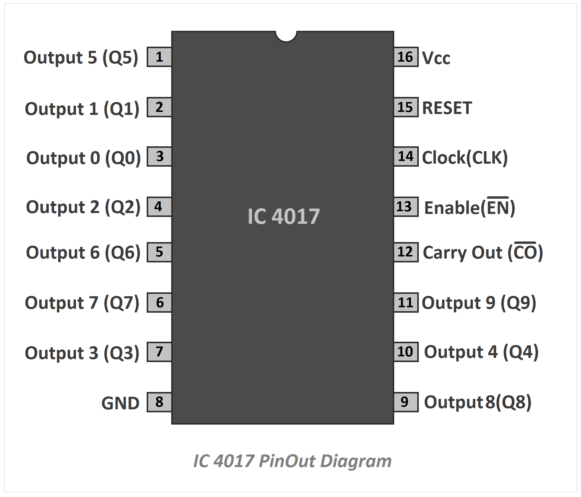
IC 4017 Pinout Diagram and Terminal Identification
IC 4017 is a counter cum decoder IC, that can count and gives decimal coded output. It is made of CMOS logic circuits. It can count from zero to ten and provides decoded output. It is mostly used in low-range counting. It has 10 separate outputs, so it can use a counter, decoder, or counter cum decoder.
Let's see the pin diagram of IC 4017
Pin No.1 - Q5 or Output 5 - The voltage at this pin will be high when the IC reads count 5
Pin No.2 - Q1 or Output 1 - The voltage at this pin will be high when the IC reads count 1
Pin No.3 - Q0 or Output 0 - The voltage at this pin will be high when the IC read count 0
Pin No.4 - Q2 or Output 2 - The voltage at this pin will be high when the IC read count 2
Pin No.5 - Q6 or Output 6 - The voltage at this pin will be high when the IC read count 6
Pin No.6 - Q7 or Output 7 - The voltage at this pin will be high when the IC read count 7
Pin No.7 - Q3 or Output 3 - The voltage at this pin will be high when the IC read count 3
Pin No.8 - Ground Pin
Pin No.9 - Q8 or Output 8 - The voltage at this pin will be high when the IC read count 3
Pin No.10 - Q4 or Output 4 - The voltage at this pin will be high when the IC read count 4
Pin No.11 - Q9 or Output 9 - The voltage at this pin will be high when the IC read count 9
Pin No.12 - Carry Out - it contains carry for the output signal. So another 4017 IC can be connected in cascade with the first 4017 IC. When we connect two ICs in cascade then we can count up to 20 numbers by the circuit. The second and last IC will be given a carry-out signal. So we can connect multiple numbers of ICs in a cascade. Each of the additional ICs will increase count capability by 10.
Pin No.13 - Enable - It is the active low pin. When this pin is connected to the ground or low voltage the IC will work normally, but when this pin is connected to high voltage the IC will stop working.
Pin No.14 - CLK - Using this pin we can give the clock pulses to the IC so, we can use it for the advanced counting.
Pin No.15 - RESET -This is the active high pin. In normal conditions, it should be connected to the ground or low voltage but if it is connected to the high voltage the IC will get reset.
Pin No.16 - Vcc - This is the power supply pin. The positive terminal of the power supply should be connected to here. Generally, 3V to 15V is to be applied to this IC.
Read Also:

