Single Phase Motor Connection Diagram and Wiring Procedure
Hey, in this article, we are going to see a Single-phase motor connection diagram and wiring procedure. An electric motor is a machine that converts electrical energy into mechanical energy or rotational motion. According to the phases of power supply, there are three types of electric motors - 1. Single Phase Motor 2. Two-Phase Motor 3. Three Phase Motor. Single Phase Motors are mostly used for domestic purposes such as ceiling fans, table fans, water pumps, washing machines, mixer grinders, etc. So, this article will help you to make wiring connections for any single-phase motor designed to operate at 230V single-phase AC supply.
Single-Phase Motor Terminal Identification
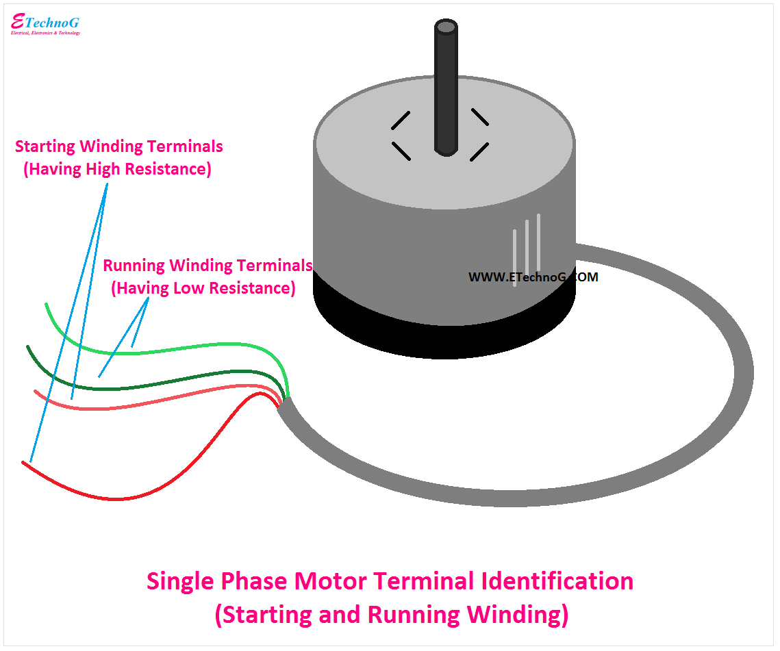
A single-phase motor is not self-starting. That is why there are two windings are used for the operation - starting winding and running winding. Starting winding is used to start or provide initial torque to the motor whereas the running winding is used to rotate the motor continuously. Both of the windings have two terminals each, so the total terminals are four(4).
Here, you can see the single-phase motor has four terminals - two red terminals and two green terminals. Now, the question is how to identify starting winding terminals and running winding terminals. It is very easy to identify. Generally, the starting winding has more resistance than the running winding.
So, take a multimeter and measure the resistance of both pairs of terminals. The terminals having more resistance is the starting winding and the winding having less resistance is the running winding. In the above figure, the red terminals are starting winding terminals and the green terminals are the running winding terminals.
Single Phase Motor Connection Diagram
Here, you can see the connection of a single-phase motor with a capacitor and power supply. Note that this is a single-phase induction Motor Wiring Diagram.
You can see the running winding of the motor is directly connected across the power supply and the starting winding is connected through a capacitor or condenser in series.
Single-Phase Motor Wiring Procedure
1. First, identify the starting winding and running winding terminals by measuring the resistance.
2. Connect any one terminal of each winding together, and it is to be connected to the neutral terminal of the power supply.
3. Connect the rest terminal of the running winding directly to the phase terminal of the power supply.
4. Connect the rest terminal of the starting winding to the phase terminal of the power supply through a series-connected capacitor.
Caution:
- There should not be any loose connection in the circuit.
- The running winding must be connected directly across the power supply, don't connect the starting winding by mistake.
- Connect the capacitor with an appropriate rating, the rating should not be very low or very high.
- Connect the operating switch with phase only.
- Always, use a circuit breaker or any protective device, if your motor is heavy and costly.
How to Change the direction of the motor?
To change the direction of the motor rotation, just interchange the terminals of any one winding either starting winding or running winding. If the terminals of both windings are changed, the motor will rotate in the same direction. Do not disturb or change other connections while interchanging the winding terminals.
Read Also:
- Difference between Generator and Alternator Full explanation.
- VFD Wiring Diagram with Motor, Switches, and External Devices
- 10 HP Squirrel Cage Induction Motor Wiring Diagram (Using CAD)
- Submersible Pump Starter and Water Level Controller Wiring Diagram
- Float Switch Connection Diagram and Wiring with Water Pump


