Comparison between RTL, DTL, and TTL Logic Families
Logic gates are the main components of any digital circuit. Almost all digital circuits are made of logic gates. These logic gates are made of transistors and other active or passive components. Here, transistors work as electronic solid-state switches. There are different classes or types of logic families according to which logic gates are built. In this article, we are going know the comparison between three common logic families that are RTL, DTL, and TTL
What is Resistor-Transistor Logic(RTL)?
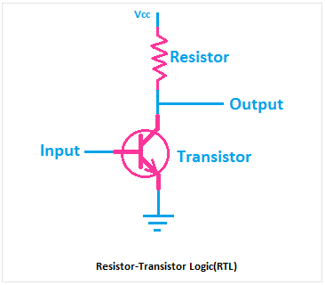
The resistor-transistor logic(RTL) is the first digital circuit to construct the logic gates. It is also known as Transistor-Resistor Logic or TRL. Here, the resistor and transistor are used to make the logic gates. The resistor is used as the input component and the transistor is used as the output component. Here, you can see a basic circuit of NOT gate using RTL Logic.
The NOT gate uses RTL logic also known as RTL inverter. The working of this circuit is very simple. When no voltage is applied to the input, the transistor acts as an open circuit so the output will be high. When the voltage is applied to the input terminal, the transistor acts as a closed circuit, so the Vcc will be grounded and the output of the circuit will be Low.
Advantages of RTL Logic
1. It is the most simple digital circuit.
2. The minimum number of transistors are required to build the logic circuit than other logic families.
3. The operation of this circuit is very simple.
Disadvantages of RTL Logic
1. Very poor response time, high propagation delay.
2. Power dissipation is high due to the resistor.
Read Also:
What is Diode-Transistor Logic(DTL)?
In the diode transistor logic, the logic gates are built with PN junction diodes and transistors. Here, diodes are used as input components and transistors are used as output components. Here, you can see the basic circuit diagram of the NAND gate using diodes and transistors.
You can see it has two input terminals and one output terminal. Let's take a condition to understand its working principle. You can see in both input terminals, diodes are connected in reverse bias. So, when both input is low the Vcc at the input side of the transistor will be grounded through the diodes and resistor. So, the transistor will be in the cutoff condition and the output of the circuit will be high.
Advantages of DTL Logic
1. Very low power dissipation.
2. Response time is better than RTL logic.
3. Fast in operation.
Disadvantages of DTL Logic
1. Types of logic gates built by DTL logic are limited.
What is Transistor-Transistor Logic(TTL)?
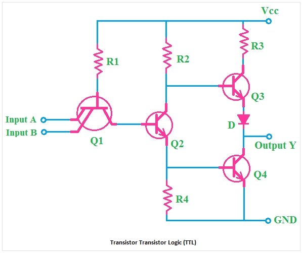
In a transistor-transistor logic, logic gates are built with bipolar junction transistors. Here, one transistor works for amplifying while another works for switching. Almost, all types of logic gates are possible to build with transistor-transistor logic. Here, you can see the basic circuit diagram of the NAND gate using TTL logic.
You can see it is a two-input circuit. The base terminal of the first transistor is connected to the Vcc and the base terminal of the second transistor is connected to the collector terminal of the first transistor. The first transistor has multiple emitter terminals. Both of the input terminals of the circuit are connected to the emitter terminal of the first transistor.
Advantages of TTL Logic
1. Provides higher reliability than other logic families.
2. Low power loss.
3. Provides amplification with switching.
Comparison between RTL, DTL, and TTL
| SL NO. | RTL Logic | DTL Logic | TTL Logic |
| 1 | Built with Resistor and Transistor | Built with Diode and Transistor | Built with Transistors |
| 2 | Slow Response | Better than RTL Logic | Much better than RTL and DTL |
| 3 | High Power Loss | Low Power Loss | Low Power Loss |
| 4 | Very simple in construction and operation | Simple in construction and operation | Complex in construction and operation |
| 5 | RTL Logic used in old computers | DTL logic is used in basic digital circuits, switching circuits | All the modern digital circuits and integrated Circuits are mostly built with TTL Logic |
Read Also:


