Circuit Breaker Wiring Diagram and Connection Procedure
A circuit breaker is an electrical protective device that provides the function to manually close a circuit and manually or automatically break a circuit. Using a circuit breaker we can manually turn off the power supply. But when the fault occurs, it will break the circuit or turn off the power supply automatically. It can not be turned on again until the fault is resolved. There are different types of circuit breakers are available according to their operation and the protection facility.
Here, we will see the connection and wiring of MCB, MCCB, and RCCB. Circuit breakers are advanced electrical protective devices used in modern electrical power circuits. The main advantages of using a circuit breaker are it is more sensitive and efficient, it is easy to operate, and remote controlling can be possible with a circuit breaker.
Miniature Circuit Breaker Wiring and Connection Diagram
A Miniature Circuit Breaker or MCB is a protective device that gives protection against overload and short circuit faults. MCB is used in low to medium-voltage and current-carrying electrical circuits. It is mostly used in domestic applications and some industrial applications. MCB comes with both voltage and current ratings but the current rating of the MCB is very important.
A proper current rating of the MCB must be considered while connecting in a circuit. If you select an MCB having a current rating less than the load current, the MCB will be tripped frequently. If you select an MCB having a current rating of very more than the load current then it will not trip when an overload fault occurs. So, the current rating of the MCB should be selected according to the load.
All of the MCBs have the identification to connect the input and output. In fact, most of the MCBs are working properly when the input supply is connected to the downside and output is taken from the upside terminals. Anyway, before connecting an MCB, you must check its input and output identification.
Molded Case Circuit Breaker Wiring and Connection Diagram
A molded case circuit breaker is the advanced version of MCB. It is specially designed for high current and high voltage electrical circuits. An MCCB also gives protection against short circuit faults and overload faults. The additional feature of the MCCB fault current adjusting. Yes, we can preset or adjust the fault current setting at which the MCCB will trip. Also, we can trip the MCCB remotely by placing a shunt trip coil in the MCCB.
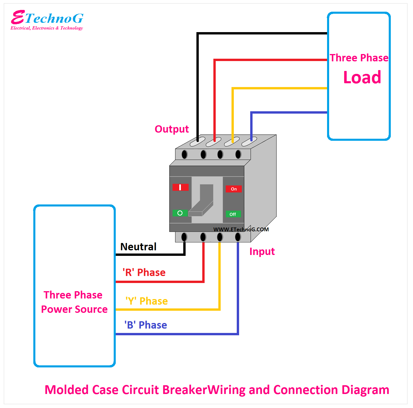
Here, you can see the connection diagram of a four-pole molded case circuit breaker. Generally, the neutral is to be connected to the first left-side terminal of the MCCB. Here, also you can see the input power supply is connected at the bottom terminals of the MCCB, and output is taken from the top side terminals.
Residual Current Circuit Breaker Wiring and Connection Diagram
The residual current circuit breaker or RCCB is a device that gives protection against leakage current fault. When a leakage current flows in a circuit, it senses and trips, so the main power gets disconnected. Remember that an RCCB cannot give protection against short circuits or overload faults.
The operating current and sensing current both are very important factors when selecting an RCCB for use. Also, note that while connecting an RCCB, both phase and neutral must go through the RCCB. If you connect the phase only and bypass the neutral, the RCCB will not work.
Read Also:
- Automatic Phase Reverse Protection Circuit using Sequence Relay
- Complete Home Electrical Protection System Wiring Diagram
- Smart WiFi Circuit Breaker Wiring Diagram and Connection Procedure
- MPCB Uses, Advantages, Connection | Motor Protection Circuit Breaker
- [Explained] Main Differences Between Relay and Contactor


