[Explained] Offline and Online UPS Block Diagram
Hey, let's see and understand UPS Block Diagram. In this article, we will discuss the Online UPS Block Diagram and Offline UPS Block Diagram. UPS stands for Uninterruptible Power Supply. UPS is used with the electronic devices which are required to keep on for some time when the main power supply is suddenly off. UPS units typically include a built-in battery that stores electrical energy. When the main power supply fails or fluctuates beyond certain predefined levels, the UPS automatically switches to battery power, providing a continuous and uninterrupted power source to connected devices. UPSs are mostly used with computers, automation devices, Servers, Networking Devices, and programming devices. So let's understand the working principle of the Uninterruptible Power Supply from the block diagram of UPS.
Online UPS Block Diagram
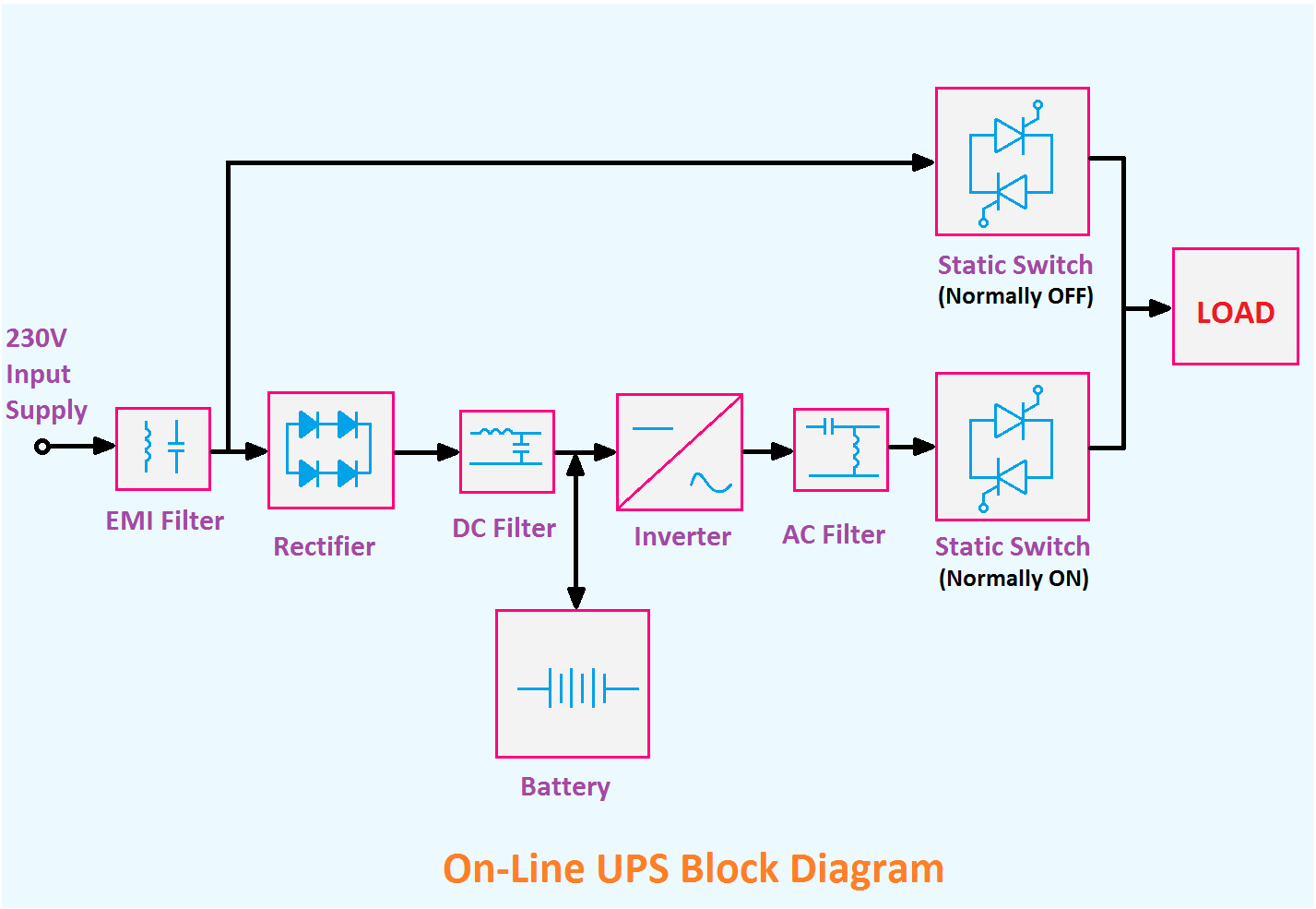
Here the block diagram of Online UPS is given below.
As you see in the above diagram, there are nine blocks are shown. Let's discuss each block.
EMI Filter: It is made using inductors and capacitors. The main function of this EMI filter circuit is to reduce or filter electromagnetic interferences.
Rectifier Circuit: The rectifier circuit is used to convert AC to DC. As the UPS has a battery inside it, and the battery can store only DC that is why we need to convert the input AC supply into DC.
DC Filter Circuit: The DC filter circuit is used to filter the impure DC that comes from the rectifier circuit. The DC output from the rectifier has some AC components. So the filter circuit is used to remove those AC components from the DC supply.
Battery: The battery is connected to the output of the DC filter circuit. When the UPS is connected to the power supply the battery will charge.
Inverter Circuit: Now we have a DC supply but, we need an AC supply as output to drive the load. So the inverter circuit is used to convert the DC to AC. The inverter Circuit is made of high-speed solid-state switches such as MOSFET, SCR, etc. If your load required DC supply then the Inverter Circuit is not required.
AC Filter Circuit: The AC filter circuit is used to filter the impure AC coming from the inverter circuit.
Static Switch: A static switch is connected between the AC filter Circuit and the Critical Load. Which allows or disallows the power flow from the UPS to load according to the given condition.
Another static switch is connected between the critical load and the main power supply after the EMI filter Supply. This switch allows or disallows the power flow from the main supply to the load.
In the case of Online UPS, the lower static switch is normally ON and the upper static is normally OFF. So in normal condition the power flow from the main supply to the load through the total UPS circuitry. When the main power supply is not available, then the load takes power from the battery.
If the UPS is unable to deliver power to the load then the upper static switch will be ON and the lower Switch will be OFF. So in this case, the power will directly flow from the main supply to the load.
Offline UPS Block Diagram
Here the block diagram of Offline UPS is given below.
You can see the block diagram of Offline UPS is the same as Online UPS. There is little difference between them. By analyzing the above block diagram, you can gain insights into how an Offline UPS operates and how it differs from the online UPS configurations.
In the case of Offline UPS, the upper static switch is normally ON and the lower static switch is normally OFF. So in normal conditions, the power directly flows from the main supply to the load. At the same time, the battery will charge. When the main power supply is not available, the upper static switch will be OFF and the lower static switch will be ON. So the load takes power from the battery.
So the static transfer switch block is a key component in an Offline UPS. It detects the presence or absence of the utility power. When the utility power is available or within acceptable limits, the switch routes the power directly to the connected devices without involving the battery or the inverter. If the utility power fails or fluctuates beyond acceptable levels, the transfer switch activates the battery backup. Other all the blocks or internal components for both online and offline ups are the same.
- Circuit Diagram of UPS or Uninterruptible Power Supply
- Proper UPS Connection with Loads, Inverter, Computer at Home
- SMPS Block Diagram | Switched Mode Power Supply
- Inverter connection diagram. Install Inverter and Battery at Home.
- Electrical Switch Board Connection Diagram and Wiring
Thank you for visiting the website. keep visiting for more updates.


