Alternator Function and Alternator Wiring Diagram in Car
The main function of an Alternator is to convert mechanical energy into electrical energy in an alternating nature. As it creates the alternating current that is why it is called an alternator. In this article, you will find the alternator function and alternator wiring diagram in a car. We know that alternator is used in cars or automobiles for charging purposes. So let's start.
Alternator Function in a Car
The alternator is used in the car to create the electrical energy to charge the battery. Initially, the engine is started in a car using a DC motor taking power supply from the battery. So there is a requirement for a charging system for the battery.
The alternator in a car is connected to the engine through a belt. So when the engine rotates the alternator also rotates and it creates electrical energy in alternating nature. The car alternator has some circuitry inside it.
Alternator Wiring Diagram
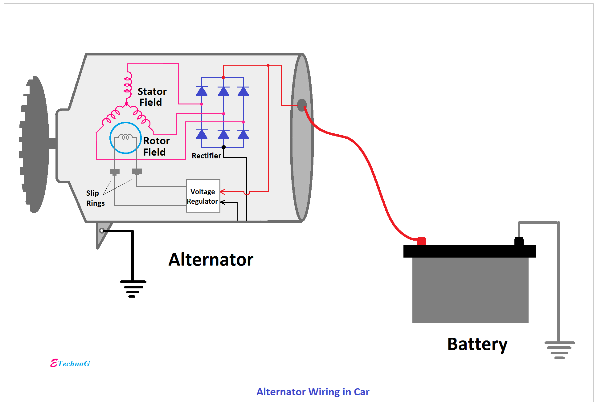
Here the basic internal circuit diagram of the car alternator and the wiring diagram of the alternator with battery is given below.
As you see there are the three-phase alternator is used in the car. The three-phase alternator has two parts stator and rotor. The stator contains the three-phase armature winding and the rotor contains field winding.
We know that the battery can store DC only. So a Rectifier circuit is placed in the alternator which converts the three-phase AC into DC.
The connection of the field winding is taken through the slip ring and is connected to a voltage regulator circuit. The voltage regulator circuit takes the DC power supply from the output of the rectifier circuit and gives it to the field winding.
The main function of the voltage regulator circuit is to control the power input to the field winding. Suppose the output voltage and current are increased above the normal value. At this time the voltage regulator will decrease the power input to the field winding hence the voltage in the armature winding will decrease and a normal value will be maintained.
Three-phase alternators are commonly used in larger vehicles, such as commercial trucks, buses, and some heavy machinery, where higher electrical power output is required to meet the demands of multiple electrical systems.
Passenger cars use a single-phase alternator (also known as a single-phase generator) to generate electrical power and charge the vehicle's battery. Single-phase alternators are simpler and more cost-effective for automotive applications, as they can provide the necessary electrical power for the vehicle's electrical systems and recharge the battery effectively. They work well with the standard 12-volt electrical systems commonly found in cars.
- 4-Pin, 5-Pin Automotive Relay Pinout and Wiring Diagram
- Car Sound System Wiring Diagram(Speaker, Amplifier, Receiver)
- Car Starter Solenoid Wiring and Connection Diagram Explained
- Ignition Switch Wiring Diagram and Connection for Pins
- How Vehicle Control Unit(VCU) Works? Learn with Block Diagram
Thank you for visiting the website. keep visiting for more updates.

