Ceiling Fan Wiring with Pull Chain Switch and Reverse Switch
Hey, in this article, we are going to see Ceiling Fan Wiring with Pull Chain Switch and Reverse Switch. We will see the wiring diagram for the ceiling fan with inbuilt light. A pull chain switch is a simple and commonly used manual control mechanism in various electrical devices such as ceiling fans, lamps, and light fixtures. It consists of a small chain or cord that you can pull to turn the device on or off, adjust its settings, or toggle between different modes.
Pull chain switches are used with ceiling fans to control their operation. Depending on the fan's design and the number of pull chains, each chain may have a different function, such as,
Power On/Off - One pull to turn the fan on, and another to turn it off.
Speed Control - Additional pulls to cycle through different fan speed settings (low, medium, high).
Light Control - If the fan has an integrated light fixture, another pull chain might control the light on/off functionality.
On the other hand, the main purpose of using a reverse with the ceiling fan is to control the direction of the ceiling fan. Using this reverse switch we can rotate the ceiling fan in forward or reverse direction.
Ceiling Fan Wiring Diagram and Connection with Pull Chain Switch
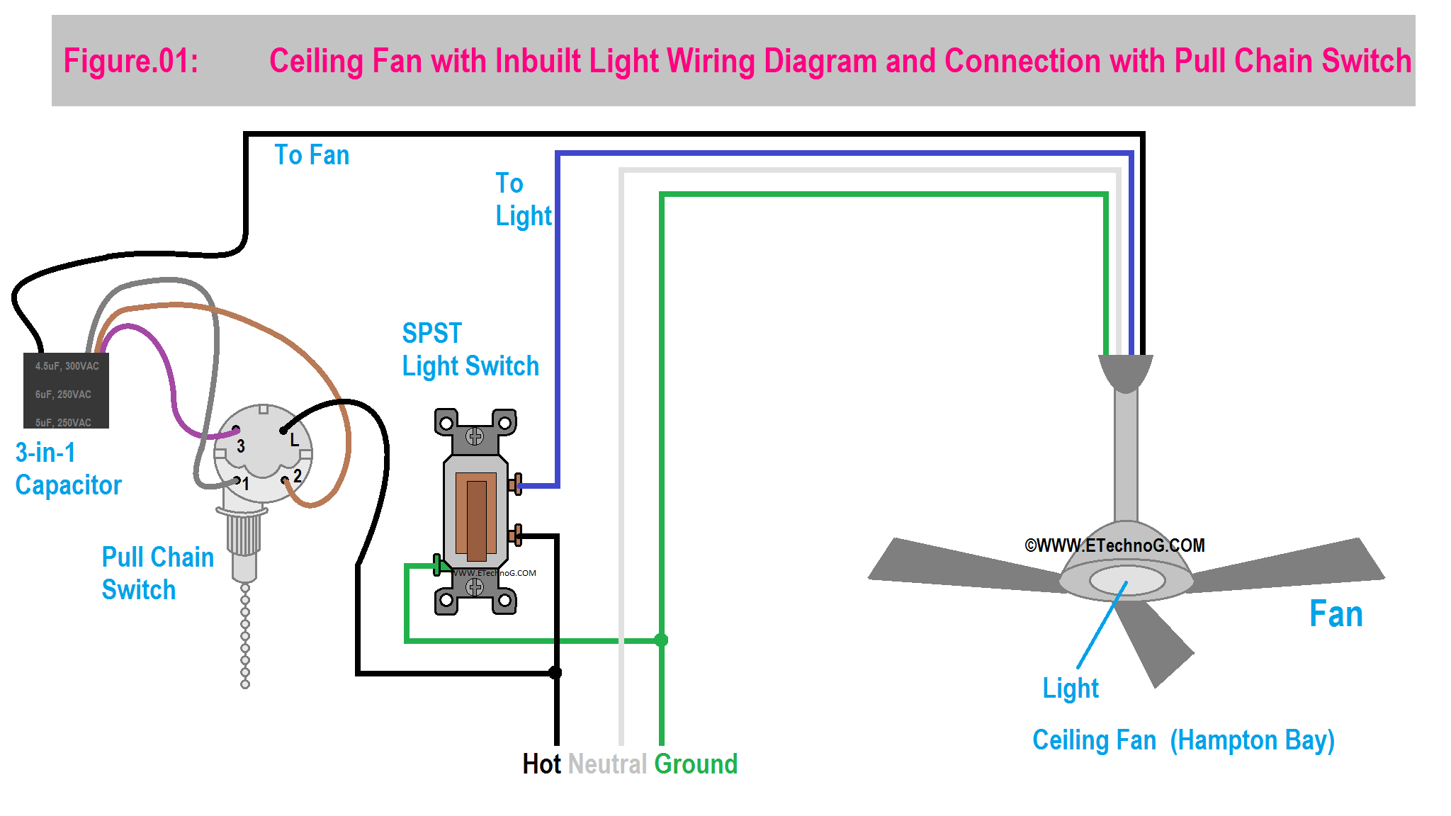
Here, you can see the wiring diagram where a ceiling fan is connected with a pull chain switch for three different speed controls.
**Remember that Capacitors, ceiling fans, and switches from different manufacturers may have different terminal identifications and color coding for wires so it is recommended to follow the user manual provided by the manufacturer**
Read Also:
Main Components
1. Pull Chain Switch
You can see the pull chain switch has terminals labeled L, 1, 2, and 3. They are commonly used for controlling the speed of a ceiling fan with three different speed settings. Each terminal corresponds to a different speed level of the fan. Here's how the connections are typically made:
The L terminal is where the incoming power supply is connected. This is usually the wire that carries electricity from your electrical panel or power source.
1, 2, and 3 Terminals represent the different speed settings of the fan. The numbers 1, 2, and 3 correspond to the low, medium, and high-speed settings, respectively.
2. 3-in-1 Capacitor
The "3-in-1" designation indicates that the capacitor allows the fan to operate at three different speed settings. Typically, these settings are labeled as "Low," "Medium," and "High." When you pull the fan's pull chain, the capacitor switches between different capacitance values, which in turn adjusts the voltage supplied to the fan motor. This variation in voltage results in different rotational speeds for the fan blades.
3. SPST Light Switch
Here a simple SPST is used to control the inbuilt light of the ceiling fan.
Ceiling Fan Wiring Diagram and Connection with Pull Chain Switch and Reverse Switch
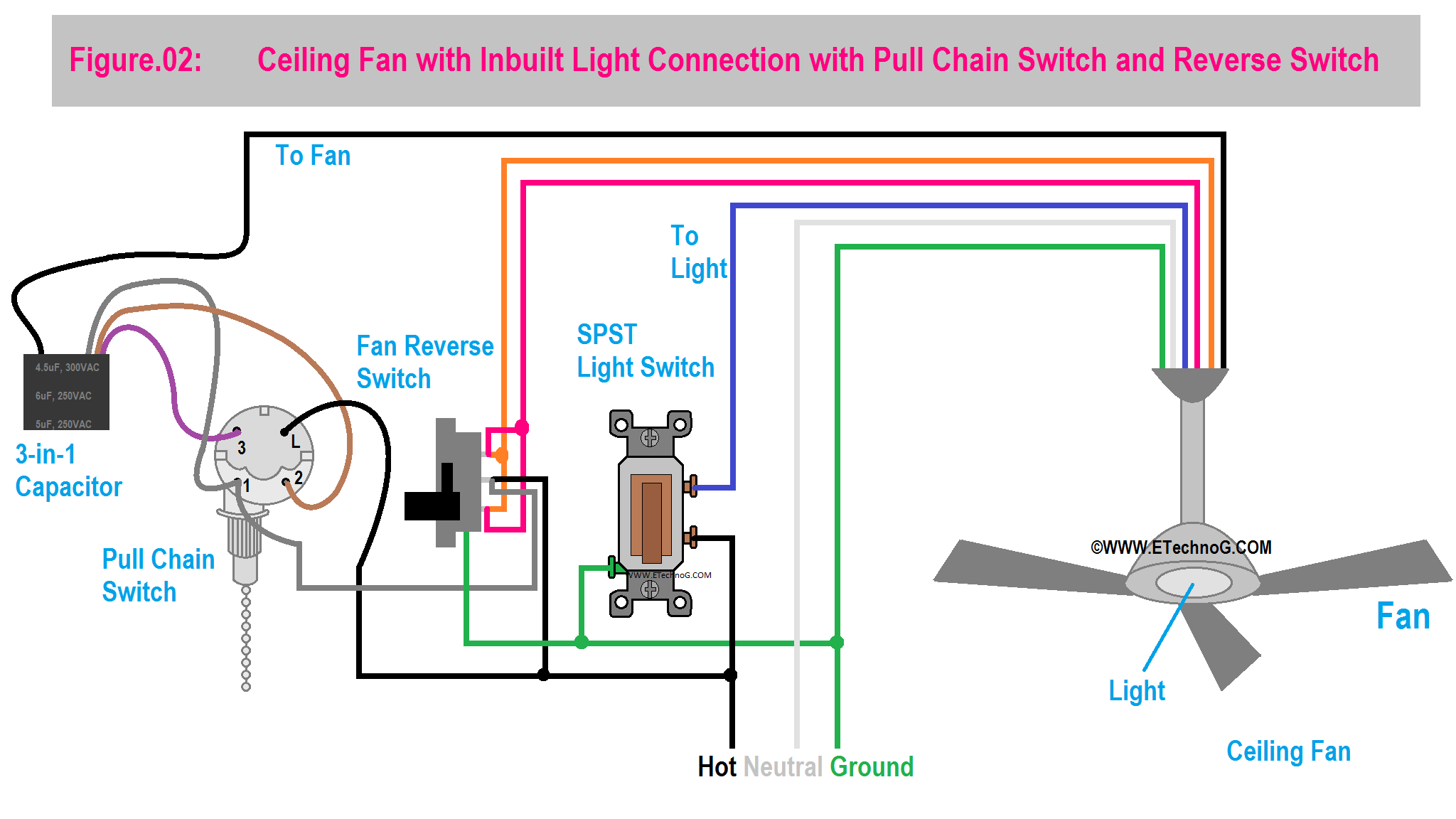
Here, you can see the wiring diagram where a ceiling fan is connected with a pull chain switch for three different speed controls and also connected to a Reverse switch to change the direction of rotation of the ceiling fan.
The reverse switch used with a ceiling fan is a mechanism that allows you to change the direction in which the fan blades rotate. Ceiling fans are designed to rotate in two different directions for different purposes: clockwise (referred to as the "winter" or "reverse" direction) and counterclockwise (referred to as the "summer" or "forward" direction).
Summer (Forward) Direction:
In the summer months, when it's warm, you want the fan to create a cooling breeze. To achieve this, the fan blades should rotate counterclockwise (in the forward direction) when you're looking up at the fan. This creates a downward airflow that can make you feel cooler by evaporating moisture from your skin.
Winter (Reverse) Direction:
In the winter months, when it's colder, you can use the ceiling fan to help distribute warm air more evenly in the room. Warm air naturally rises, and if you have high ceilings, this can result in a temperature difference between the floor and ceiling. By reversing the direction of the fan blades to rotate clockwise (in the reverse direction), you can gently push the warm air near the ceiling back down into the living space, improving overall room comfort.
Both Ceiling Fan and Ligh Connection with Pull Chain Switch
Here, you can see the wiring diagram where the ceiling fan and the inbuilt light, both are connected to their respective pull chain switches.
A pull chain switch for Light is generally used to control the attached light source. For example, A single pull turns the light on, and another pull turns it off. Some pull chain switches might have multiple settings, allowing you to control the brightness or color temperature of the light if the fixture supports those features.
Read Also:


