Spectrum Analyzer Block Diagram and Important Parts
In this article, we are going to see the block diagram of Spectrum Analyzer and its important internal parts. A Spectrum Analyzer is an electronic Measuring instrument that is used to analyze an electronic signal in the frequency domain. It shows the amplitude of the signal with different frequency representations. It shows the amplitude and frequency representation on its CRT Display or Screen. It uses two axes to represent the amplitude and signal. The X-axis (horizontal axis) represents the Frequency of the signal and the Y-axis (verticle axis) represents the Amplitude of the signal.
Spectrum Analyzer is used in laboratories, electronic testing, RF signal handling, electronic design, etc. There is a little difference between the Oscilloscope and Spectrum Analyzer. The oscilloscope displays the amplitude of the signal with respect to the time domain whereas the spectrum analyzer displays the amplitude representation with respect to the frequency domain.
Basically, there are two types of Spectrum Analyzer,
- Filter Bank Spectrum Analyzer
- Superheterodyne Spectrum Analyzer
The superheterodyne type is more efficient and is widely used.
Block Diagram
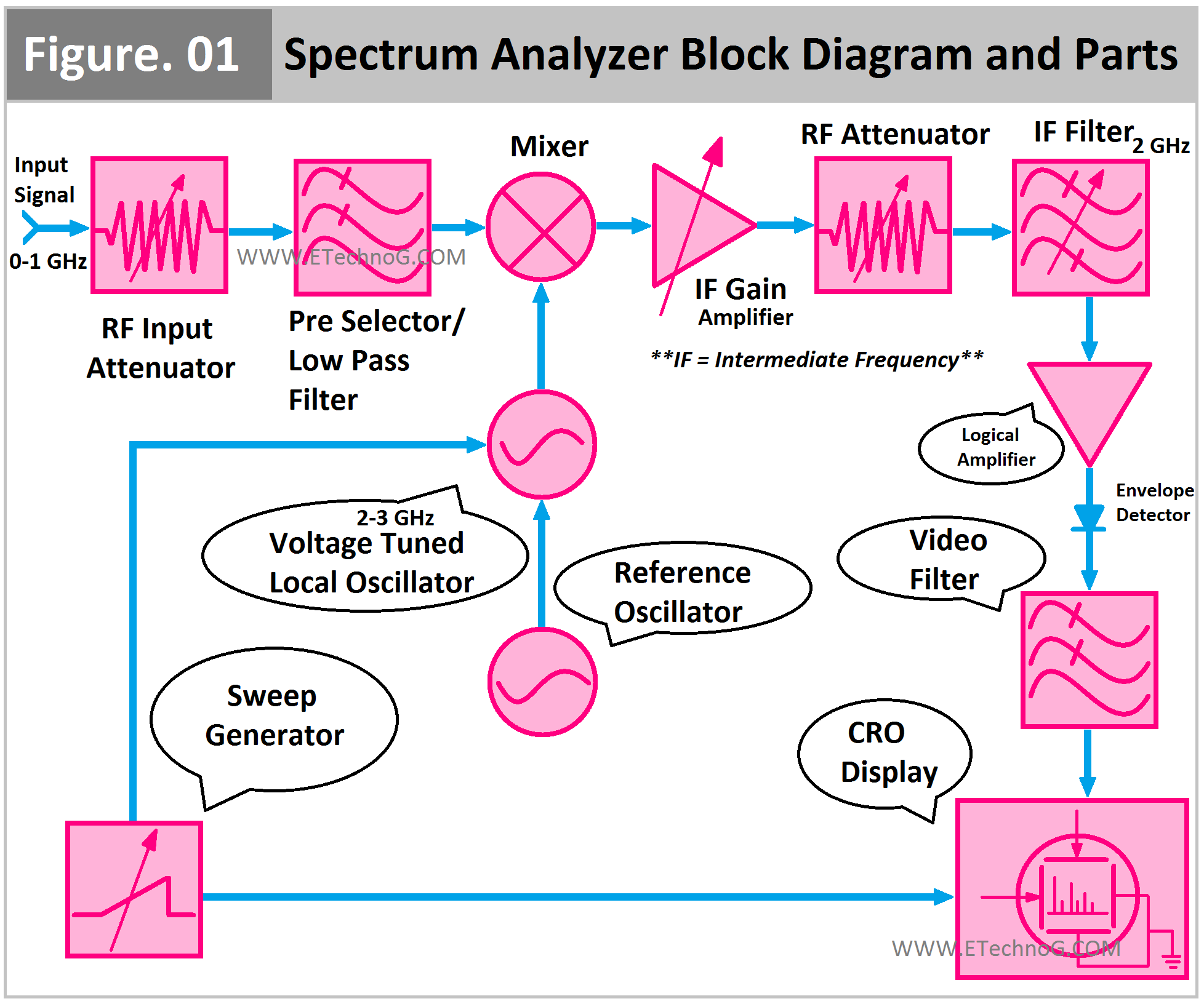
Here, you can see the Superheterodyne Spectrum Analyzer Block Diagram and its important Parts.
Important Parts
Input Attenuator
Every analyzer is designed to analyze or is capable of taking input up to a certain amplitude of the signal. If the signal has very amplitude then there will be a chance of Overloading, Disturbance, and Gain Reduction. So the RF Input Attenuator is used to attenuate the input signal. It is done automatically by a pre-set reference limit when the signal is entered into the device. Also, we can manually set the reference limit. The input attenuator works as a protection device for the whole system.
Pre Selector or Low Pass Filter
This unit blocks very high-frequency signals. Or we can manually set the frequency limit. So up to a certain level of frequency signal can enter into the device. It is just opposite to the input attenuator. The attenuator blocks the high amplitude whereas the low pass filter blocks the high frequency.
Mixer
The mixer unit has three ports - two input ports and one output port. It takes input from the actual input signal through the low pass filter and the reference input from the voltage-tuned local oscillator. The mixer mixes those two signals and generates a new output signal. The frequency of the generated output may either be the addition of the frequency of two input signals or the difference between the frequency of the two input signals. The frequency of the output signal from the mixer is called intermediate frequency.
Intermediate Frequency(IF) Gain Amplifier
It is a variable gain amplification device. Basically, it is used to adjust the vertical position of the signal without altering the signal level of the mixer input. It is coupled with the input attenuator, so it is easy to avoid the variation in reference level with the change in applied input.
RF Attenuator
It is used to attenuate the signal coming from the Intermediate Amplifier. It is not an essential part of the system. Even it is not used with all devices.
Intermediate Frequency(IF) Filter
It is basically a Band Pass Filter. It allows the signal to have a frequency within a certain range. The bandwidth level of the IF Filter is termed as the resolution bandwidth of the entire device. By varying the resolution bandwidth the sensitivity can be varied.
Detector
The function of the detector is to transform the IF signal from the IF filter into either a video signal or a baseband signal. This converted signal will get more digitalized through the analog-to-digital converter so it can be represented on the vertical axis of the CRO Display.
Video Filter
It is basically a low-pass filter. It helps to remove the noise from the video signal so the smooth video traces can be shown on the display.
Sweep Generator
It is basically an electrical waveform generator in different formats such as a sawtooth wave. It provides the signal to the local oscillator and to the CRT display for tunning purposes.
Read Also:
Thank you for visiting the website. keep visiting for more updates.

