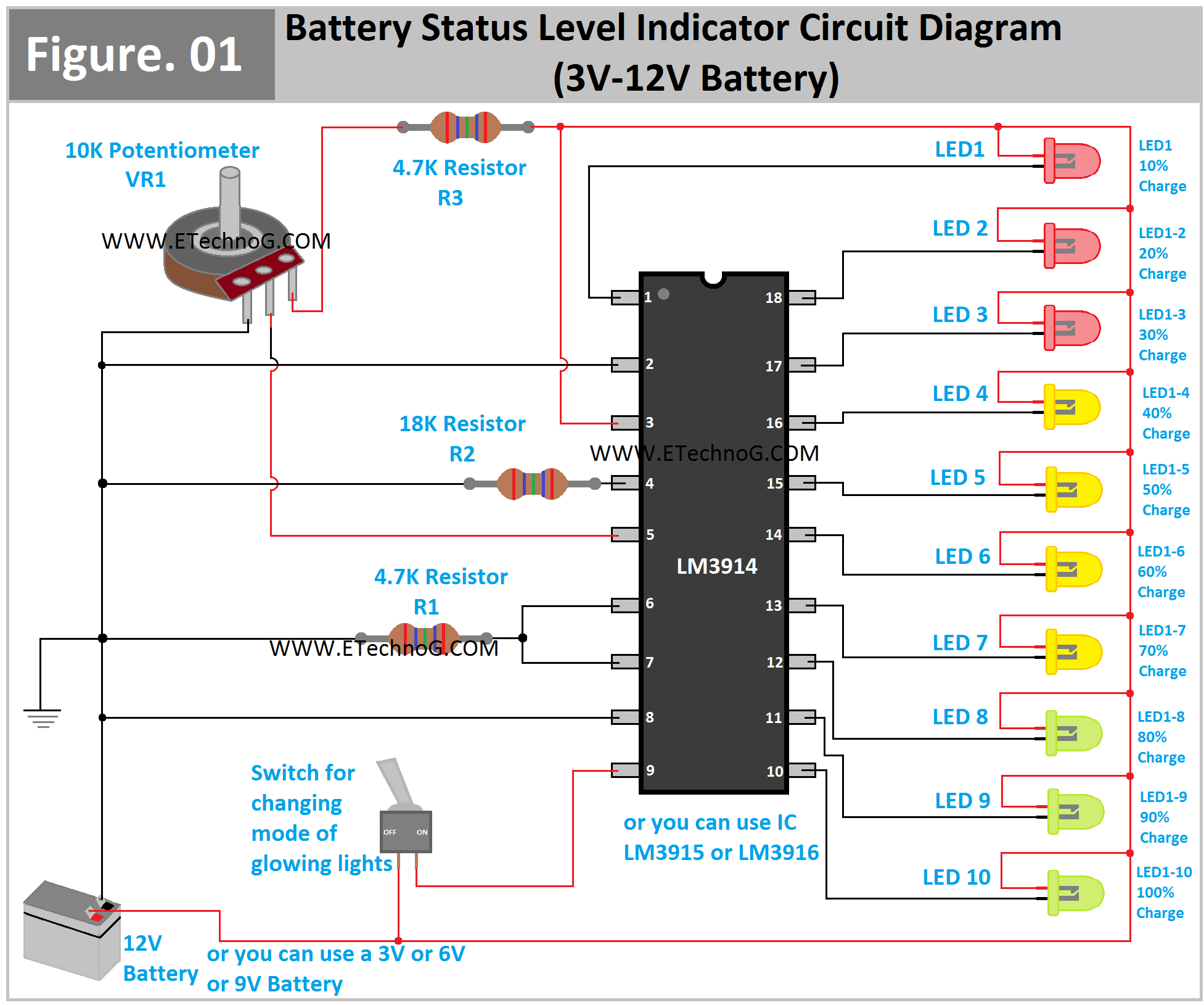
Battery Status Level Indicator Circuit Diagram (For 3V-12V Battery)
Here, in this article, we are going to see a circuit diagram for battery status or battery level indication. This circuit will indicate how much charge is available in the battery. The circuit is designed with the IC LM3914 for use from 3V to 12V or 15V batteries. As the IC LM3914, LM3915, and LM3916 have the same specifications, so you can use those ICs also. This circuit is very easy to connect and it gives a satisfactory output. Anyway, let's see the circuit diagram, list of components required, and connection procedure.
Battery Level Indicator Circuit Diagram using IC LM3914
Here, you can see the circuit diagram and connection between the IC and each component.
List of Required Components
- 1 PCs IC LM3914 or LM3915 or LM3916
- 10 Pcs LEDs(you can take all the same colors or different color like us)
- One SPST Switch
- One 10K Potentiometer
- 2 Pcs 4.7K resistors
- 1 Pcs 18K resistor
- From 3V to 12V any battery for testing
Connection Procedure
- Connect all the Positive terminals of the LED together and finally connect with pin no 3 of the IC. And this pin 3 should be connected to the positive terminal of the power source or battery.
- Remember that we count the LED glowing from low voltage to high voltage. That means the LED1 will glow at the lowest voltage or and the LED10 will at the highest voltage.
- Pin no 1 of the IC is to be connected to the LED1 and Pin no 10 of the IC is to be connected to the LED10. LED2-LED9 is to be connected from Pin No 18 to Pin No 11 respectively which means the LED number increased while Pin No decreased. See the circuit diagram for more clarification.
- Connect one terminal of the switch to pin no 9 of the IC and another terminal of the switch is to be connected to the positive terminal of the source or battery.
- Short the pins 6 and 7 and finally connect them to the negative or ground terminal in series with a 4.7K resistor.
- Connect pin 4 to the negative or ground terminal with an 18K series resistor.
- Connect the middle terminal of the potentiometer to pin no 5 of the IC.
- Connect the left side terminal of the potentiometer to the negative terminal of the power source or battery.
- Connect the right side terminal of the potentiometer to the positive terminal of the battery with a series resistor of 4.7K.
Operation and Working Principles of the Circuit
Before connecting the battery you need a power supply with a small voltage to set the percentage of indication of the circuit. For example, apply a 1.2V power supply to the circuit. Now rotate the potentiometer knob until the LED1 glows properly. So you have set that each LED will glow for every 1.2V difference. As there are ten numbers of LEDs show each LED will show 10% of the maximum voltage. Now connect a battery to the circuit. If your battery has a 2.4V voltage then LED1 and LED2 will glow. If your battery has 12V all the LEDs will glow.
Here is the list of different battery voltages with respective glowing LEDs with percentages.
| Number of LED Glowing | Percentage of Voltage Indicating (Battery Status) | Battery Voltage Indicating (if 12V battery connected) |
| LED1 | 10% | 1.2V |
| LED1,2 | 20% | 2.4V |
| LED1, 2,3 | 30% | 3.6V |
| LED1, 2,3,4 | 40% | 4.8V |
| LED1, 2,3,4,5 | 50% | 6.0V |
| LED1, 2,3,4,5,6 | 60% | 7.2V |
| LED1, 2,3,4,5,6,7 | 70% | 8.4V |
| LED1, 2,3,4,5,6,7,8 | 80% | 9.6V |
| LED1, 2,3,4,5,6,7,8,9 | 90% | 10.8V |
| LED1, 2,3,4,5,6,7,8,9,10 (all LEDs ON) | 100% | 12V |
Read Also:

