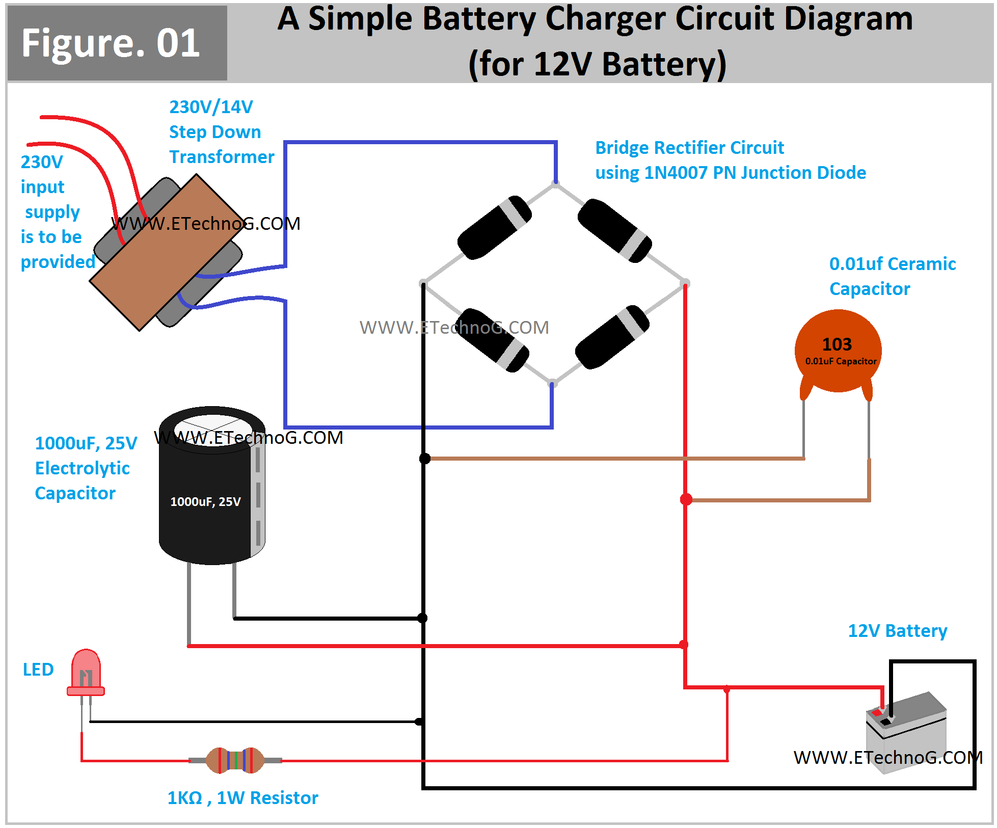
A Simple Battery Charger Circuit Diagram for 12V Battery
In this article, we are going to see a simple circuit diagram of a battery charger circuit for a 12V battery. Also, we will see the connection between each component and their connection procedure. The battery charger is basically an electronic circuit that helps to provide the proper voltage and current to the battery to restore its charge or voltage level. Here, the battery charger circuit is shown, basically a rectifier circuit with some additional components. All the battery charger circuits are the rectifier circuit it does not mean. Our utility power supply is 120V or 230V AC supply. So to charge a 12V battery we need a 13V to 14V DC power supply. So these charger circuits step down the 230V AC supply into 14V AC and convert it into a DC supply.
Battery Charger Circuit Diagram
Here, you can see the circuit diagram of a 12V battery charger.
List of Required Components
- A 230V/14V Step Down Transformer or you can use a 120V/14V transformer if your country has a 120V utility power supply
- 4 PCs 1N4007 PN Junction Diodes
- 1 Pcs 0.01uF Ceramic Capacitor
- 1 Pcs 1000uF, 25V Electrolytic Capacitor
- 1 Pcs 1 Kiloohm, 1Watt Resistor
- 1 Pcs LED
- A 12V battery that needs to be charged
Connection Procedure
- Connect all the PN junction diodes in the form of a bridge, see the above circuit diagram for more clarification. Don't forget to identify the anode and cathode terminal before connecting. The white market side is the cathode.
- Connect the transformer output terminal(low voltage side) to the bridge rectifier circuit. Here, also refer to the above diagram.
- Connect the 0.01uF ceramic capacitor in parallel with the output of the rectifier circuit. Here, the polarity of the connection doesn't matter.
- Also, connect the electrolytic capacitor in parallel with the output of the rectifier circuit. Connect the positive terminal of the capacitor to the positive terminal of the rectifier and the negative terminal of the capacitor to the negative terminal of the rectifier.
- Connect the 1-kiloohm resistor in series with the LED and the whole combination of this LED and resistor should be connected in parallel with the output of the rectifier circuit. Remember that the negative terminal of the LED should be connected to the negative terminal of the rectifier and the positive terminal of the LED should be connected to the positive terminal of the rectifier through the resistor.
- Now the final output from the circuit can be connected to the battery for charging. The positive terminal of the charger circuit should be connected to the positive terminal of the battery and the negative terminal of the charger circuit should be connected to the negative terminal of the battery.
Working Principle
The step-down transformer helps to step down the high-voltage power supply into a low-voltage power supply(in this case 230V into 14V). But the output of the transformer is also an AC supply. So the bridge rectifier circuit using diodes is used to convert the alternating power from the output of the transformer into direct power. The electrolytic capacitor smoothens the DC power supply coming from the rectifier circuit. The ceramic capacitor is used to ground the unwanted high-frequency alternating noise signal. Here, the LED is used to indicate either the circuit providing output power.
Read Also:

