Half and Full Subtractor Truth Table, Circuit Diagram
In digital electronics, a subtractor is a combinational logic circuit built with different types of logic gates whose primary function is to perform the subtraction of two bits. These two buts are known as minuend and the other is the subtrahend. In some applications such as arithmetic operations in calculators, computers, and other digital devices, subtractor circuits are used. I may want to make sure that you already know what is a bit in digital electronics. Just simply remember that when the voltage level is high it is considered as 1 and when the voltage level is low it is considered as 0. Basically, these 0 and 1 bits are provided alternatively to the input of the subtractor circuit and after the operation, it provides the output.
What is Half Subtractor?
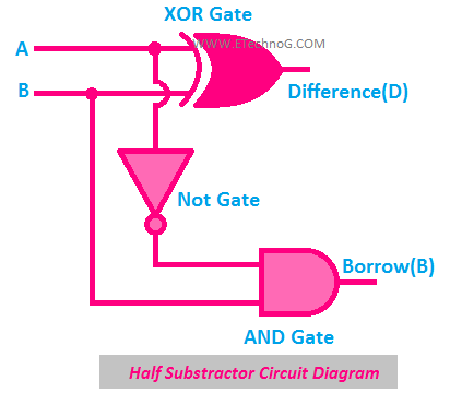
A half subtractor is a simple circuit built with a single XOR, NOT, and AND gate that subtracts only two numbers.
The main drawback of the subtractor circuit is it does not take borrowing into account.
Half Subtractor Logic Symbol
Here, you can see the logical symbol of Half Subtractor. You can see here, it has two input terminals (input A and input B) and two output terminals (Difference-D and Borrow-B).
Half Subtractor Circuit Diagram
Here, you can see the circuit diagram of the half subtractor. You can see it is built with one XOR gate, one NOT gate, and one AND gate. Basically, the AND gate is connected in parallel with the XOR Gate in series with the NOT gate. The output of the XOR gate provides the value of the difference and the output of the AND gate provides the value of the borrow.
Half Subtractor Truth Table
Here, you can see the truth table of half subtractor. Basically, it has four columns as there are two inputs and two outputs. Also, it also has four rows as four combinations possible for two inputs.
According to the above truth table, the boolean expression of the half subtractor is,
Difference(D) = A ⊕ B
Borrow(B) = A' B
Read Also:
What is a Full Subtractor?
A full Subtractor is a combinational logic circuit that subtracts two bits by taking borrow into account from the previous adjacent lower minuend bit.
So you may understand the main advantage of a full subtractor over a half subtractor is it takes the borrow into account during its operation.
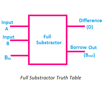
Full Subtractor Logic Symbol
Here, you can see the logic symbol of full subtractor. You can see it has three input terminals(Input A, Input B, and Borrow In-Bin). It has two outputs - Difference(D) and Borrow Out(Bout).
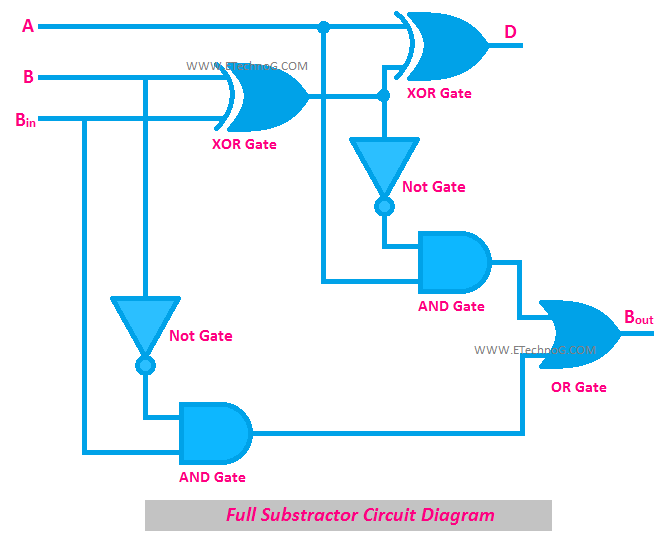
Full Subtractor Circuit Diagram
Here, you can see the circuit diagram of Full Subtractor. You can see it is built with two XOR gates, two NOT gates, two AND gates, and one OR gate.
Basically, the full subtractor is the combination of two half subtractors. They are combined by an OR gate. We know that the half subtractor provides two outputs - difference(D) and borrow(B). So the difference output of the first half subtractor is provided to the first input of the second half subtractor and the borrow output of the first half subtractor is provided to the second input of the second half subtractor. The difference output of the second half subtractor is considered as the final difference output of the whole full subtractor circuit. On the other hand, the final borrow output comes from an OR gate whose inputs are fed from the borrow output of the birth first and second half subtractor.
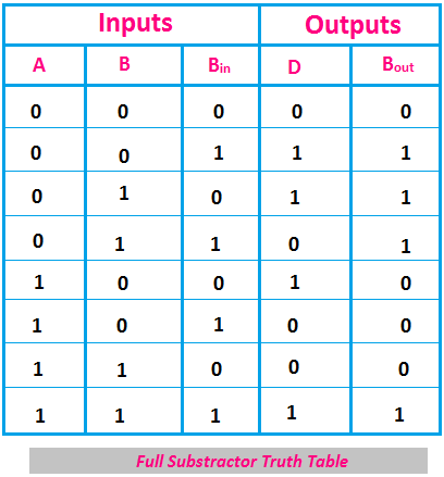
Full Subtractor Truth Table
Here, you can see the truth table of full subtractor. You can see, it has five columns as it has three inputs and two outputs. It has eight rows as eight input combinations are possible from three input variables.
According to the above truth table, the boolean expression of full subtractor is,
Difference(D) = A ⊕ B ⊕ Bin
Borrow Out(Bout) = A' Bin + A' B + B Bin
Borrow Out(Bout) = A' Bin + A' B + B Bin
Read Also:


