Ethernet Cable Wiring Diagram with Color Code for Cat5, Cat6
If you are searching for an ethernet cable wiring diagram with a connector and proper color code then you came to the right place. We know there is a huge of applications of ethernet cable in networking systems. Generally, we required an Unshielded Twisted Pair ethernet cable of at least Category 5 or Cat 5 for basic gigabit operation. For a higher data transferring system cat 6 is the best. There are different types of ethernet cable such as,
- Category 5 or Cat5 Cable
- Category 5e or Cat5e Cable
- Category 6 or Cat6 Cable
- Category 6e or Cat6e Cable
- Category 7 or Cat7 Cable
The color coding for almost all the category cables is the same. The category mainly differed the speed or capacity.
Generally, you will find two types of ethernet cable such as solid and braided stranded cable. Stranded ethernet cable is much better than solid cable for some applications such as patch applications. On the other hand, the solid ethernet cable is used for the longer run.
The wiring of the ethernet follows two different standards such as T-568A and T-568B. In these two standards, the arrangement of colored pairs varies.
For the wiring of ethernet cable, generally, 8P8C connectors are used. These connectors are named as RJ45 connectors. RJ stands for registered jack. These connectors have 8 pins and they are designed to connect with solid ethernet cables. In the wiring, basically, we have to connect two connectors at both side two ends with proper color codes.
Ethernet Wiring Diagram with Color Code(T-568A)
Here, you can see the wiring diagram of the T-568A Ethernet cable system. You can see at both ends, that the T-568A connector is used.
In the above diagram, you can see the color codes corresponding to the pin numbers. And in the below table, you can see the function or signal for each pin. Make sure that the copper strips are toward your face when you match the connection same as in the above diagram.
Table for T-568A
| RJ 45 Pin | Color Codes | Function/Signal |
| 1 | White/Green | Data Transmit+ |
| 2 | Green | Data Transmit- |
| 3 | White/Orange | Data Receive+ |
| 4 | Blue | Unused |
| 5 | White/Blue | Unused |
| 6 | Orange | Data Receive- |
| 7 | White/Brown | Unused |
| 8 | Brown | Unused |
Ethernet Cable Wiring Diagram with Color Code(T-568B)
Here, you can see the wiring diagram for the T-568B ethernet cable. Here, you can see at both ends, that the T-568B connector is used.
Follow the below table for the function of each pin corresponding to color codes.
| RJ 45 Pin | Color Codes | Function/Signal |
| 1 | White/Orange | Data Transmit+ |
| 2 | Orange | Data Transmit- |
| 3 | White/Green | Data Receive+ |
| 4 | Blue | Unused |
| 5 | White/Blue | Unused |
| 6 | Green | Data Receive- |
| 7 | White/Brown | Unused |
| 8 | Brown | Unused |
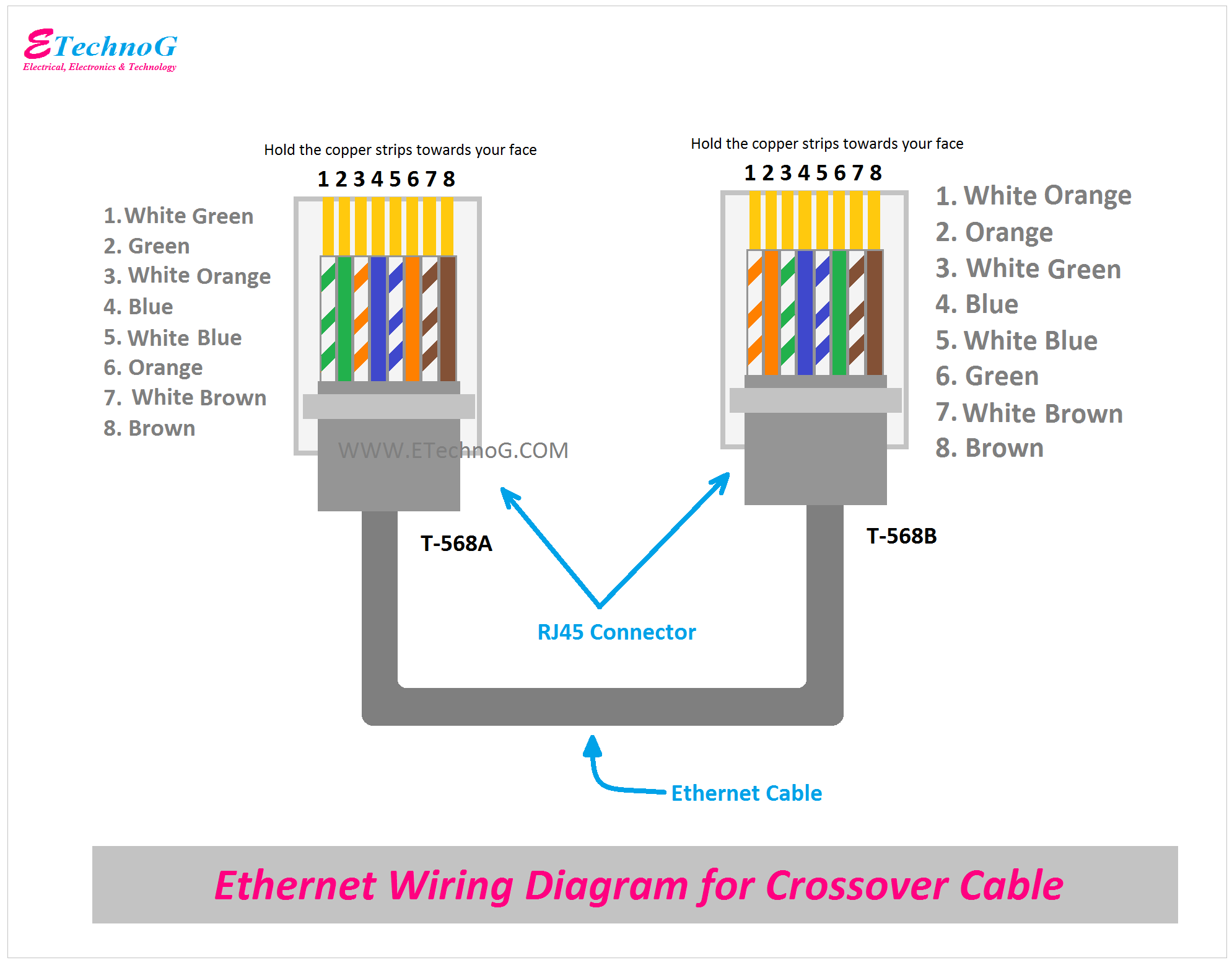
Ethernet Wiring Diagram for Crossover Cable
Here, you can see the wiring diagram for the crossover cable. You can see here, that at one end T-568A connector is connected whereas on the other end T-568B connector is connected.
Here is the table, you can see the function and color code for both connectors.
| RJ 45 Pin | End 1 T-568A Color Codes | Function/Signal | End 2 T-568B Color Codes |
| 1 | White/Green | Data Transmit+ | White/Orange |
| 2 | Green | Data Transmit- | Orange |
| 3 | White/Orange | Data Receive+ | White/Green |
| 4 | Blue | Unused | Blue |
| 5 | White/Blue | Unused | White/Blue |
| 6 | Orange | Data Receive- | Green |
| 7 | White/Brown | Unused | White/Brown |
| 8 | Brown | Unused | Brown |
How to wire Ethernet Cable with Connectors
Here is the step-by-step procedure to connect an RJ45 jack with the ethernet cable.
- First of all, strip out the outer sheath of the cable by about 2 inches.
- Untwist the twisted wire and make straight all the wires.
- Now arrange and align all the single wires colorwise as per the above wiring diagrams.
- Trim all the wires with the same length but don't forget to leave 1/2" exposed from the sheath.
- Now insert all the wires into the RJ45 Jack with the proper pin number and color codes. Also, recheck that all the wires are fully inserted into the jack.
- Crimp the RJ45 Jack with a crimping tool.
- After crimping, recheck all the wires are properly crimped and connected.
- Now connect the another RJ45 jack at the other end by following the same procedure.
- After connecting both the RJ45 jack your wiring is ready.
Read Also:


