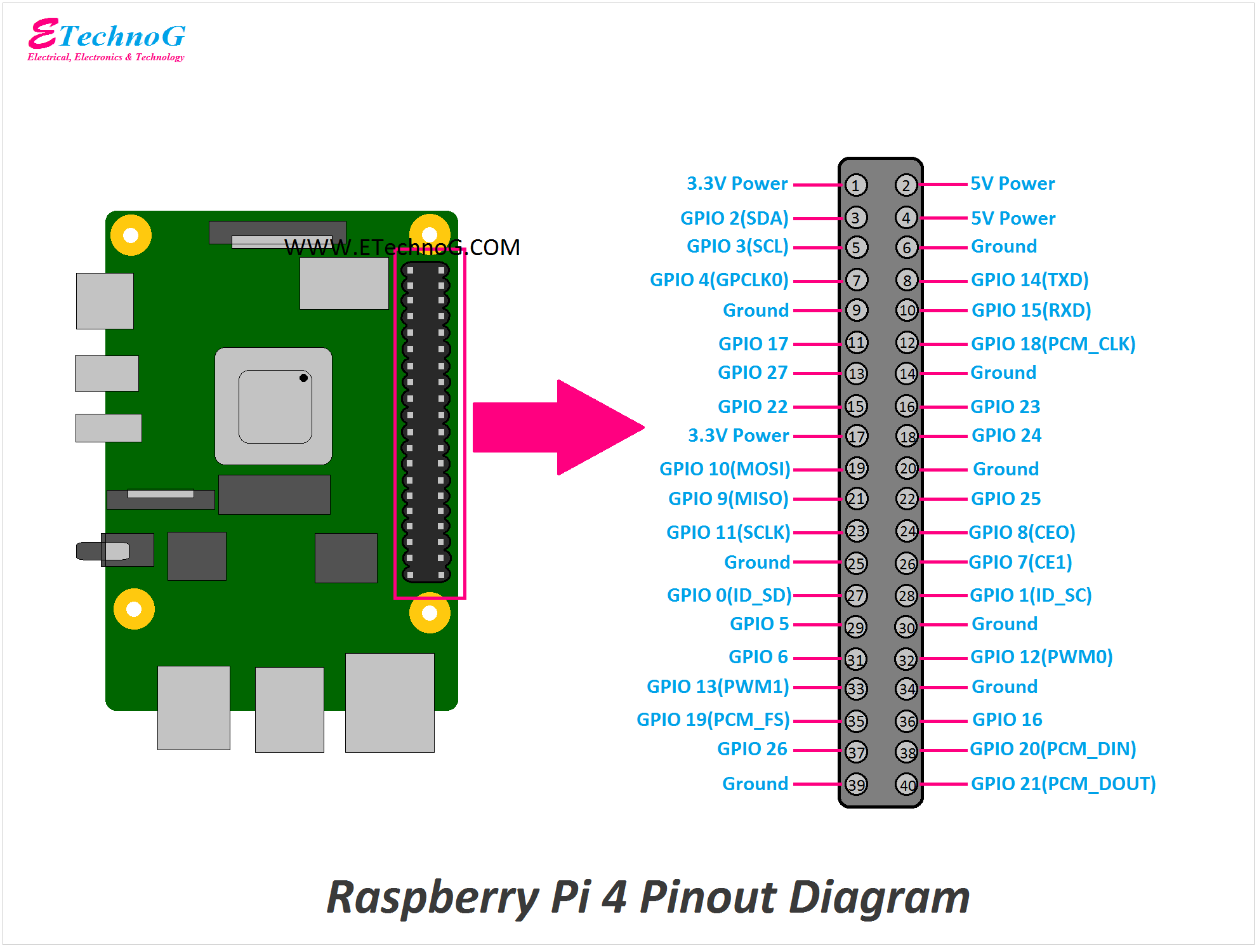
Raspberry Pi 4 Pinout Diagram and Terminals Identification
Power Supply Pins
Power IN
Power OUT
- Pin No 6
- Pin No 9
- Pin No 14
- Pin No 20
- Pin No 25
- Pin No 30
- Pin No 34
- Pin No 39
Digital Input/Output Pins
GPIO0 – Pin No 27
GPIO1 – Pin No 28
GPIO2 – Pin No 3
GPIO3 – Pin No 5
GPIO4 – Pin No 7
GPIO5 – Pin No 29
GPIO6 – Pin No 31
GPIO7 – Pin No 26
GPIO8 – Pin No 24
GPIO9 – Pin No 21
GPIO10 – Pin No 19
GPIO11 – Pin No 23
GPIO12 – Pin No 32
GPIO13 – Pin No 33
GPIO14 – Pin No 8
GPIO15 – Pin No 10
GPIO16 – Pin No 36
GPIO17 – Pin No 11
GPIO18 – Pin No 12
GPIO19 – Pin No 35
GPIO20 – Pin No 38
GPIO21 – Pin No 40
GPIO22 – Pin No 15
GPIO23 – Pin No 16
GPIO24 – Pin No 18
GPIO25 – Pin No 22
GPIO26 – Pin No 37
GPIO27 – Pin No 13
Serial Communication and UART Pins
The GPIO pins of this module can be used for other functions such as communication purposes. Here the list of pins through serial and UART communication can be done.
TXD1 – GPIO14 – Pin No 8
RXD1 – GPIO15 – Pin No 10
TXD2 – GPIO0 – Pin No 27
RXD2 – GPIO1 – Pin No 28
TXD3 – GPIO5 – Pin No 29
RXD3 – GPIO4 – Pin No 7
TXD4 – GPIO8 – Pin No 24
RXD4 – GPIO9 – Pin No 21
TXD5 – GPIO12 – Pin No 32
RXD5 – GPIO13 – Pin No 33
SPI Communication Pins
Here, is the list of SPI Communication Pins through which controlling devices can be connected that use SPI Protocols.
SPI3 CEO N – GPIO0 – Pin No 27
SPI3 MISO – GPIO1 – Pin No 28
SPI3 MOSI – GPIO2 – Pin No 3
SPI3 SCLK – GPIO3 – Pin No 5
SPI4 CEO N – GPIO4 – Pin No 7
SPI4 MISO – GPIO5 – Pin No 29
SPI4 MOSI – GPIO6 – Pin No 31
SPI4 SCLK – GPIO7 – Pin No 26
SPI0 CE1 N – GPIO8 – Pin No 24
SPI0 CE0 N – GPIO9 – Pin No 21
SPI0 MISO – GPIO10 – Pin No 19
SPI0 MOSI – GPIO11 – Pin No 23
SPI5 CEO N/ SPI0 SCLK – GPIO12 – Pin No 32
SPI5 MISO – GPIO13 – Pin No 33
SPI5 MOSI – GPIO14 – Pin No 8
SPI5 SCLK – GPIO15 – Pin No 10
CTS0 – GPIO16 – Pin No 36
RTS0 – GPIO17 – Pin No 11
SPI6 CEO N – GPIO18 – Pin No 12
SPI6 MISO – GPIO19 – Pin No 35
SPI6 MOSI – GPIO20 – Pin No 38
SPI6 SCLK – GPIO21 – Pin No 40
I^2C Communication Pins
SDA0/SDA6 – GPIO0 – Pin No 27
SCL0/SCL6 – GPIO1 – Pin No 28
SDA1/SDA3 – GPIO2 – Pin No 3
SCL1/SCL3 – GPIO3 – Pin No 5
SDA3 – GPIO4 – Pin No 7
SCL3 – GPIO5 – Pin No 29
SDA4 – GPIO6 – Pin No 31
SCL4 – GPIO7 – Pin No 26
SDA4 – GPIO8 – Pin No 24
SCL4 – GPIO9 – Pin No 21
SDA5 – GPIO10 – Pin No 19
SCL5 – GPIO11 – Pin No 23
SDA5 – GPIO12 – Pin No 32
SCL5 – GPIO13 – Pin No 33
SDA6 – GPIO22 – Pin No 15
SCL6 – GPIO23 – Pin No 16
Pulse Width Modulation(PWM) Pins
PWM0 – GPIO12 – Pin No 32
PWM1 – GPIO13 – Pin No 33
PWM0 – GPIO18 – Pin No 12
PWM1 – GPIO19 – Pin No 35
SD Card Input/Output Pins
SD0CLK/SD1 CLK – GPIO22 – Pin No 15
SD0 CMD/SD1 CMD – GPIO23 – Pin No 16
SD0 DATA0/SD1 DAT0 – GPIO24 – Pin No 18
SD0 DAT1/SD1 DAT1 – GPIO25 – Pin No 22
SD1 DAT2/SD1 DAT2 – GPIO26 – Pin No 37
SD0 DAT3/SD1 DAT3 – GPIO27 – Pin No 13
- Raspberry Pi Pico Pinout Diagram and Raspberry Pi Pico W
- PLC Sinking and Sourcing Module Input Output Connection Diagram
- DHT11 / DHT22 Sensor Pinout, Circuit, and Wiring Diagram
- RFID RC522 Pinout and Interfacing with Arduino for Door Lock System
- Color Sensor TCS34725 Pinout Diagram and Connection with Arduino

