PIR Motion Sensor Wiring and Connection Diagram for Installation
Hey, in this article, we are going to learn how to install a conventional PIR Motion sensor. Also, we will see the wiring and connection diagram of a PIR Motion Sensor. PIR means Passive Infrared Sensor. A PIR motion sensor is one that can sense moving objects, humans, or animals. Motion sensors are mostly used for automatic light on/off, automatic sliding doors open and closing, etc. You can see the applications of motion sensors in shopping malls, theaters, canteen, meeting places, etc. In fact, you can install a motion sensor in your own home too. Nowadays, compact motion sensors are available in the market. You do not need to make any complex electronic circuitry.
Motion Sensor Terminal and Function
Here, you can see the terminal diagram of a conventional PIR motion sensor available in the market.
This motion sensor works at a 230V AC supply. It is a compact device. The actual motion sensor, ICs, Relays, and everything are available inside this compact device. You can see there are a total of three terminals - Phase(P), Neutral(N), and Load(L). Overall, it will work as a Normally Open(NO) contact in the circuit. Generally, the 230V AC supply is to be connected across the P and N terminals. In normal conditions, there is no movement near the sensor and no voltage in the Load or 'L' terminal. When there is a movement near the sensor the 230V supply will be available in the 'L' terminal.
Motion Sensor Wiring and Connection
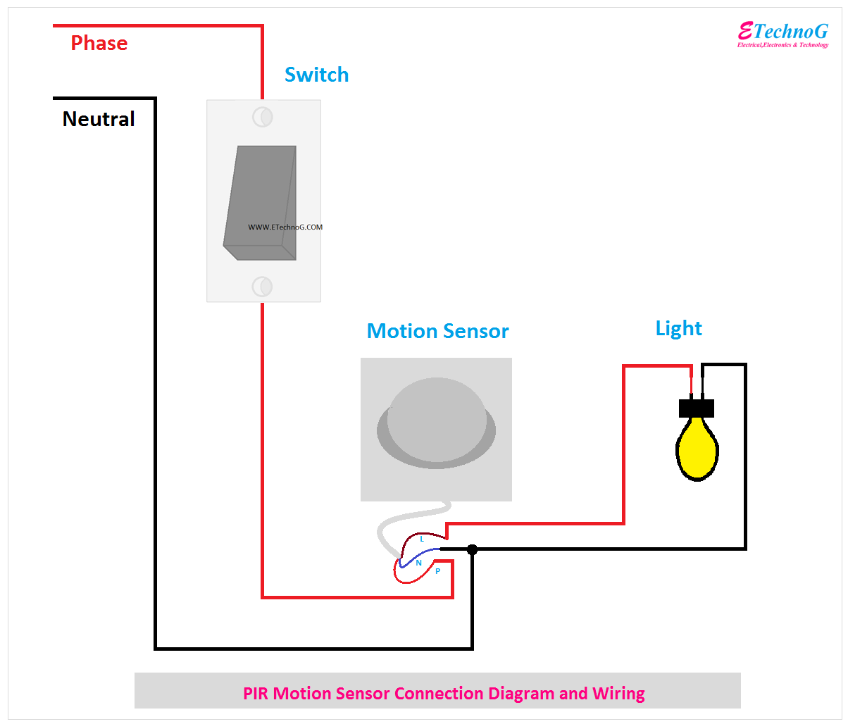
Here, you can see the connection diagram of motion sensor with light and power supply.
Connection Procedure
1. Connect the neutral terminal of the power source to the neutral terminal(N) of the sensor and the neutral terminal of the Light or bulb.
2. Connect the phase terminal of the power source to any terminal of the switch.
3. Connect another terminal of the switch to the phase terminal of the sensor.
4. Connect the Load Terminal(L) of the Sensor to the phase terminal of the light.
Working of automatic light Using a Motion Sensor
Now let's discuss how this circuit works. When the switch is in off condition, no current or voltage is applied to the circuit, so the light will never turn on until the switch is turned on.
When you turn On the switch, the circuit will be charged. The sensor acts as a NO contact. When a person comes near the sensor or any movement happens within the range of the sensor, the sensor will act as an NC or closed contact. So the light will get the power supply from the load terminal of the sensor. So, you can turn On the switch at night time or in a dark time. Also, you can use an LDR instead of that switch, so this circuit will work in the dark time only.
Motion Sensor Installation Procedure
1. The motion sensor must be projected at the movement side or application area.
2. The average range of a motion sensor is up to 6 meters. So, install or place the sensor within 6 meters of the application area.
3. There is no obstacle in front of the motion sensor. Also always clean the sensor to increase its range, and working efficiency.
Read Also:


