DOL Starter Connection and Wiring Diagram with OLR
In this article, we are going to see the DOL Starter Connection and Wiring Diagram including the Thermal Overload Relay and indication circuits. DOL starter or Direct Online Starter is the most simple method to start a low-capacity three-phase motor. It connects the motor directly to the power supply. The main function of a DOL starter is to turn on or turn off a motor. But a DOL starter is also designed to trip the circuit or disconnect the motor from the power supply when an overload fault occurs. DOL starters are mainly used with low-capacity three-phase induction motors.
DOL Starter Connection
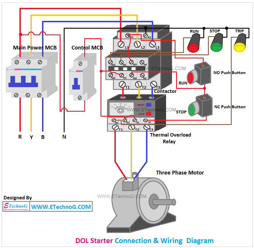
Here you can see the connection diagram of a DOL starter with overload protection. Click on the image to enlarge.
Different parts of this Wiring,
MCB
Here you can see two MCBs are used for this circuit. A three-pole MCB is the main power MCB through which the main three-phase power supply for the motor is provided. Another one is a Single Pole MCB for the control circuit. When the control MCB is turned On, the control circuits will be charged. So to operate this DOL starter, first, you have to turn on the main power MCB and then the Control MCB.
Contactor
The contactor is the main component of a DOL Starter that actually connects and disconnects the motor from the power supply. Here you can see a three-pole contactor is used. This contactor has three power contacts and four auxiliary contacts. The magnetic coil of this contactor is designed to operate at 230V AC supply.
Thermal Overload Relay
Here a three-phase thermal overload relay is used. This relay has one NC contact and one NO contact.
Push Button Switches
Here two push button switches are used. One NC Push Button(Green Colour) to turn off the motor and one NO Push Button(Red Colour) to turn on the motor.
Indication Lamps
Here you can see we have used three indication lamps for indication purposes. Red for ON, Green for OFF, and Yellow for Trip.
So when the motor is in off condition, then only the green lamp will glow, when the motor is in On condition then only the red lamp will glow, when the motor is tripped due to overload then both green and Yellow lamps will glow.
Procedures to make DOL Starter Wiring
First of all, you have to select Contactor, Overload Relay, and Switches with proper ratings. So, you can refer to this article - Sizing The DOL Motor Starter Parts (Contactor, Fuse, Circuit Breaker and Thermal Overload Relay)
Power Circuit
1. Connect the main incoming three-phase power supply to the main power MCB as per the diagram.
2. Connect the outgoing of the power MCB to the Contactor incoming terminals L1, L2, and L3.
3. Connect the incoming terminals of the overload relay with the contactor outgoing terminals T1, T2, T3
4. Connect the motor terminals to the overload relay outgoing terminals as per the diagram.
Control Circuit
1. Take a loop from the R phase for the control circuit and connect the control MCB as per the diagram.
2. Connect the neutral wire to the Contactor A2 terminal and also to one terminal of each indication lamp.
3. Connect the NO and NC contacts of the contactor to the control MCB outgoing as per the diagram.
4. Connect the NO. NC contacts of the overload relay to the control MCB outgoing as per the diagram.
5. Connect NO and NC push button switches as per the diagram.
6. Connect Indication lamps as per the diagram.

