Optocoupler Types, Applications with Examples and Circuit Diagrams
An optocoupler is a component that uses light energy to connect two different electrical circuits or transfer energy from one circuit to another circuit. Two circuits are completely electrically isolated to each other which means there is no electrical connection between them. In this article, we will discuss
Optocouplers have also some different names such as Opto-isolator, optical isolator, photocoupler, etc.
Optocoupler mainly comes within ICs. IC 4N35, IC PC817, and other 4NXX series ICs are examples of optocoupler ICs.
Let's see what is inside an optocoupler IC.
Optocoupler Construction
As you see in the above figure the Optocoupler IC is divided into two sections, one is the Light emitter section and another section is a light receiver or light sensor. The optocoupler mainly has two elements one is a light source, which may be LED, LASER, Infrared, etc. Another element is a light receiver such as it may be a Phototransistor.
We know that when a light is applied to the base of the phototransistor it conducts current. This principle is used in the optocoupler. So when we give electricity to the optocoupler then it creates a light that may be visible or Infrared and it is false upon the base of the transistor hence the transistor starts conducting current.
When the applied light is off then the transistor stops conducting.
Different Types of Optocoupler
1. Photo-Transistor Optocoupler
As you see in the above diagram the photo-Transistor Optocoupler has an IR LED as a light source and a phototransistor as a light sensor or light receiver.
In The terminals optocoupler, the 6th no pin is connected to the base of the transistor to control the sensitivity.
2. Photo-Darlington Optocoupler
In Photo-Darlington, two transistors are used. When IR light falls upon the base of one transistor it turns on the other transistor.
3. Photo-SCR Optocoupler
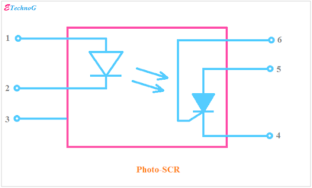
As you see in the above figure, the Photo-SCR Optocoupler uses an SCR inside it. When the light falls upon the gate of SCR it will turn ON. To control the sensitivity the gate terminal of the SCR is connected to 6th no. pin.
4. Photo-DIAC Optocoupler
5. Photo-TRIAC Optocoupler
Examples of Optocoupler ICs
Example of Photo-Transistor Optocoupler IC, PC816, PC817, LTV817, K847PH
Example of Photo-Darlington Optocoupler IC, 4N32, 4N33, H21B1, H21B2, H21B3
Example of Photo-TRIAC Optocoupler IC, IL420, 4N35
Example of Photo-SCR Optocoupler IC, MOC3071, IL400, MOC3072
Example of Photo-DIAC Optocoupler IC, MOC3020, MOC3021
Applications of Optocoupler
1. The main application of optocoupler is to isolate two different electrical circuits.
2. Optocouplers are used in solid-state relays.
3. Optocouplers are used for ground isolation purposes.
4. Optocouplers are used for high-voltage monitoring and sensing circuits.
5. Optocouplers are used in lamp dimmer circuits.
6. Optocouplers are also used in Motor control circuits.
7. Optocouplers are used in lighting control circuits.
8. Optocouplers are used in switch mode power supply(SMPS)
9. Optocouplers are used in DC to DC converter circuits in automobiles.
Motor Control Circuit using Optocoupler
The motor control circuit using a Photo-DIAC optocoupler is given below.
You can see in the above circuit diagram, that pins 1 and 2 of the optocoupler are connected to a DC source through a switch and a resistor.
The motor is connected to the AC supply through a TRIAC. Here the Photo-DIAC optocoupler is used to trigger the TRIAC.
When we turn ON the switch, the IR LED inside the optocoupler will turn on and the light falls upon the DIAC. When the DIAC starts conducting, the TRIAC will be triggered, therefore the motor will turn on.
As you see the high-voltage AC circuit and low-Voltage DC circuit are isolated to each other by the Optocoupler.
Read Also:
- Solid State Relay Applications, Advantages over Normal Relay
- IGBT Symbol, Circuit, Characteristics, Constructional Diagram
- Difference between Analogue, Digital, and Power Electronics
- Solenoid Function difference with Coil, Inductor, Electromagnet
- 5V Relay Modules Pinout Diagrams (Single, Dual, Multi-Channel)
Thank You For Visiting the Website. Keep Visiting for more updates.


