[Explained] Electronic Ballast Circuit Diagram and Working
Here you will find the electronic ballast circuit diagram with the explanation of the working principle. Here I have given the circuit diagram of Electronic Ballast with proper indication and explained each part of the circuit. Here you also find the block diagram of electronic ballast which will help you too much to understand the electronic ballast circuit.
Electronic Ballast Block Diagram
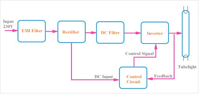
There are many manufacturing companies that make electronic ballasts. Their circuit diagrams of electronic ballast are different. But all of them maintain the actual block diagram of the electronic ballast. If you completely understand the block diagram then you can easily understand the electronic ballast circuit of any company. The simple block diagram of the electronic ballast is given below.
As you see in the above figure there are a total of five blocks in the block diagram of the electronic ballast. Generally, all the electronic ballasts follow that block diagram.
Block 1: Block 1 represents the EMI(Electromagnetic Interference) filter. EMI filter consists of some inductor and capacitor which block or reduces electromagnetic interference.
Block 2: Block 2 represents the rectifier circuit. The rectifier circuit is used to convert AC to DC.
Block 3: Block 3 represents the DC filter circuit. The DC filter circuit consists of a Capacitor which filters the impure DC coming from the rectifier circuit.
Block 4: Block 4 represents the inverter circuit. In this block, the DC is converted into high-frequency AC, and there is a step-up transformer which increases the voltage level.
Block 5: Block 5 represents the control circuit, which takes feedback from the output and controls the rectifier, filter, and inverter circuits. Most of the electronic ballasts not have this block.
Circuit Diagram of Electronic Ballast
Here you can see the circuit diagram of Electronic Ballast. Each block is indicated. EMI filter, Rectifier, DC filter, and Inverter are shown in this circuit diagram. To know the workings of this circuit read the working principle section.
Working Principle of Electronic Ballast
As you see in the above circuit diagram of electronic ballast, first a series resistor is connected. It is connected to limit the overload and short circuit current. In some electronic ballast, a fuse is used instead of a series resistor. This resistor has a very low value up to 22 Ohm.
Next, an electromagnetic interference filter circuit is connected. The EMI filter consists of one inductor in series and one capacitor in parallel.
Then a bridge rectifier circuit is used to convert AC to DC. The Bridge Rectifier Circuit consists of four PN Junction Diode.
A Capacitor is connected in parallel for the filtering purpose of impure DC coming from the rectifier circuit.
An inverter circuit using two transistors is used. The transistors create high-frequency AC and give to the step-up transformer. The frequency created in electronic ballast is 20 KHz to 80 KHz. Generally, the transistor creates a square wave AC signal. The step-up transformer increases the voltage level up to 1000V. At the starting time, the voltage across the tube light is 1000V. Once the tube light glows the voltage across it decrease to 230V and the electronic ballast allow to flow a low current to the tube light.
Read Also:
- What is an electrical choke, Why electric choke use in Fluorescent tube light
- Why Fluorescent Light with Electronic Ballast does not need Starter?
- [Explained] Connection of Tube Light with Diagram
- Circuit Diagram of UPS or Uninterruptible Power Supply
- Mosquito Killer Bat Circuit Diagram and Working Principle
- Working of modern Led bulb with transformer less power supply.
Thank you for visiting the website. keep visiting for more updates.


