Digital Wattmeter Connection Diagram and Wiring Procedure
Hey, in this article we are going to see the connection diagram of Digital Wattmeter. We will see the both Single Phase and Three Phase Digital Wattmeter Connection Diagram. These types of digital wattmeters are mostly used in electrical panels. Wattmeter is basically a measuring instrument that is used to measure electrical power. We know that electrical power is the combination of both voltage and current so the wattmeter needs both the voltage and current input. Generally, the single-phase wattmeter does not need the CT connection but the three-phase wattmeter needs the CT connection for the power measurement. Of course, for a very high current single-phase or two-phase system we need to use Current Transformers.
Single Phase Digital Wattmeter Connection Diagram
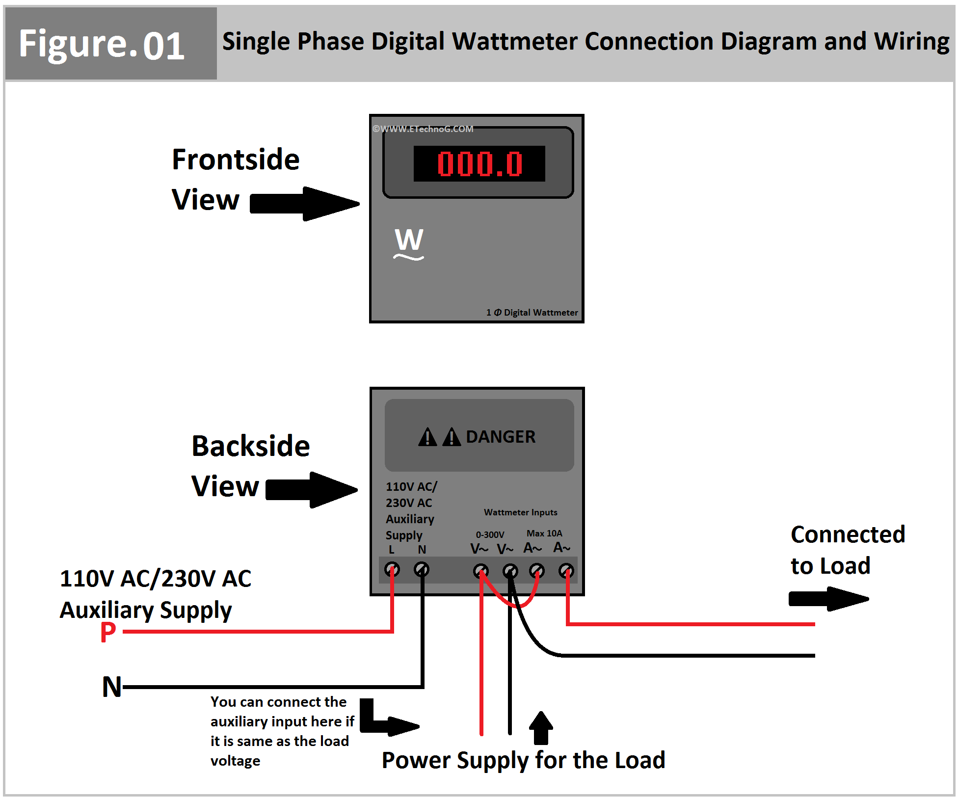
Here, you can see the Connection Diagram of Single Phase Digital Wattmeter.
Connection Procedure
- Connect the 230V or 110V auxiliary power supply to the wattmeter as per your meter requirement. There will be two separate terminals for the auxiliary power supply connection in the wattmeter.
- Now connect the power supply terminals to the wattmeter that is used to drive the load circuit. Connect both phase and neutral terminal to the wattmeter voltage input terminals that may be identified as voltage input or P.C Coil.
- Now another two terminals need to be connected that may be identified as Current input or C.C coil. We need to connect the CC coil in series with the load circuit.
- So, connect any one terminal of the CC coil to the phase terminal of the power source. Connect another terminal of the CC coil to the phase terminal of the Load Circuit.
- Connect the neutral terminal of the load circuit directly to the neutral terminal of the power source.
Three(3) Phase Digital Wattmeter Connection Diagram
Here, you can see the connection diagram of Three(3) Phase Digital Wattmeter.
Three Phase Digital Wattmeter needs a CT connection. Here, in the above wiring diagram, you can see two CTs are connected. One is connected to Line 1 or R phase and the other one is used to Line 3 or 'B' Phase. This is because the wattmeter works on the principle of Electrical power measurement using two wattmeter method. Here, the neutral connection is not required for power measurement. Remember that this connection is only suitable for three phase three-wire load.
Connection Procedure
- Connect the auxiliary power supply to the meter. You can connect any external power source or from the existing three-phase power source by taking any one phase and neutral.
- Now, connect all the there phase lines from the power source(that is used to drive the load) to the wattmeter voltage input terminals identified as R, Y, B or L, L2, L3. Dont, interchange any phases.
- Now connect the CT1 that is connected with the 'R' phase to the CT1 terminal of the wattmeter that may be identified as CT1 or A1.
- Similarly, connect the CT3 that is connected with the 'B' phase to the CT3 terminal of the wattmeter which may be identified as CT3 or A3.
Read Also:


%20Digital%20Wattmeter%20Connection%20Diagram%20and%20Wiring.png)