Digital to Analog Converter (DAC) Block Diagram, Working
DAC or Digital to Analog Converter is an electronic circuit or device that converts a digital signal into an analog signal. A digital signal is discrete in time and amplitude or mostly available in the form of binary such as 0 or 1. On the other hand, the analog signal is continuous in amplitude and time. There are both methods Analog to digital conversion(ADC) and Digital to Analog Conversion(DAC) are used in electronic systems. The ADC method is used when any physical quantity is converted into an electronic signal and used to process and the DAC method is used when the electrical or electronic signal is converted to a physical quantity. You will see the applications of the DAC in an electronic telecommunication system, automation system, measurement system, etc.
Digital-to-analog conversion is more difficult and complex than analog-to-digital conversion. In the analog-to-digital conversion process signal cutting or power removal happens whereas in the digital-to-analog conversion signal or power addition happens. Generally, the digital-to-analog converter, or DAC allows multiple inputs and a single output. It basically converts the discrete time-discrete amplitude signal into a continuous time-continuous amplitude signal.
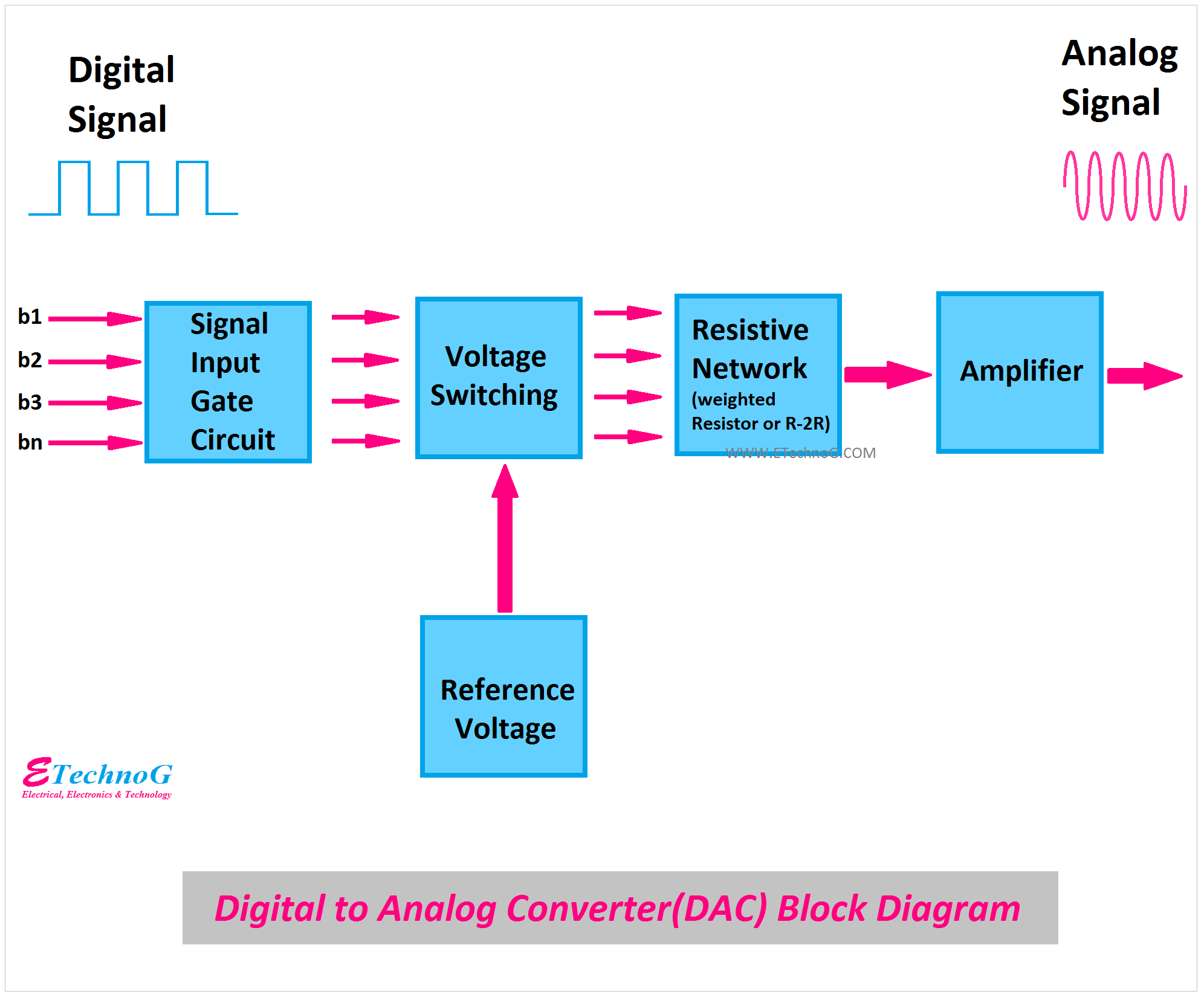
Digital to Analog Converter (DAC) Block Diagram
Here, you can see the block diagram of DAC or Digital to Analog Converter.
The main blocks or parts of a Digital to analog conversion system are,
Input Circuit
It receives the binary digital inputs safely and does some process or filtration if required. It does not have any vital role in the whole circuit.
Voltage Switching Circuit
It switches voltages between input digital signals and reference voltage sources and passes to the main resistive circuit. It also makes a connection or isolation with the ground.
Resistive Network
It is the main part of the digital-to-analog converter circuit. It basically helps with multiple digital input processing before the amplifier circuit. There are two types of DAC available according to the resistive network - weighted resistor network and R-2R network. The r-2R network has more advantages than the weighted resistor network.
Amplifier
Generally, a differential or operational amplifier is used in the DAC system. That not only amplifies the signal even it also makes a differentiate or comprises signal or process signal such as summation, etc.
How Digital to Analog Converter(DAC) Works?
As we know there are two types of DAC, A weighted resistor network can generate an analog signal almost equal to the input digital signal. It works with an inverting adder circuit. The main disadvantage of the weighted resistor network is the difference between the resistance value will increase with the increasing of bits in the input digital signal corresponding to LSB & MSB.
On the other hand, the R-2R network has so many advantages over the weighted resistor network. It also generates the analog signal almost equal to the input binary digital signal. The main advantage of the R-2R network is that it contains only two values of resistors R and 2R so it is very easy to design and easy to select the resistor during the operation. Also, the difference between the resistor values during the increase of the number of bits in the signal can be adjusted by adding R-2R sections.
Read Also:

