Three Phase Motor Connection Diagram and Wiring Procedure
Hey, in this article we are going to see the three-phase motor connection diagram and wiring procedure. Three-phase motors are those that operate with a 440V three-phase AC supply. Three-phase motors are mostly used in industrial, travel, and vehicle applications.
Three-phase motors are working in the principle of electromagnetic induction. They have a stator and a rotor winding. generally, the stator winding is designed to operate with a three-phase AC supply. When a three-phase power supply is applied to the stator winding, it produces a rotating magnetic field. This rotating magnetic field causes to produces an emf on the rotor winding as well as magnetic fluxes.
The interaction between the rotor magnetic flux and the stator rotating magnetic flux will create a torque on the rotor, thus the rotor rotates. Remember that three-phase motors are self-starting, they do not require any capacitor for the starting.
Internal Connection of Three-Phase Motor
Three-phase motors have three separate winding and each of them has two terminals. So the total terminal of the three-phase motor is six(6). Before, connecting a three-phase motor with the power supply, we have to connect the terminals of the motor in a star connection or delta connection. Here, you can see the diagram, of how we can connect the terminals of a three-phase motor in a star or delta connection.
The terminals of the upper motor are not connected. The left side motor is Star connected and the right side motor is delta connected. The motor has three windings and six terminals such as (U1, U2), (V1, V2), and (W1, W2). To connect the motor in a star configuration, connect U1, V1, W1 together or U2, V2, W2 together. Here, in the above diagram U2, V2, and W2 are connected together and U1, V1, and W1 are used to connect the power supply.
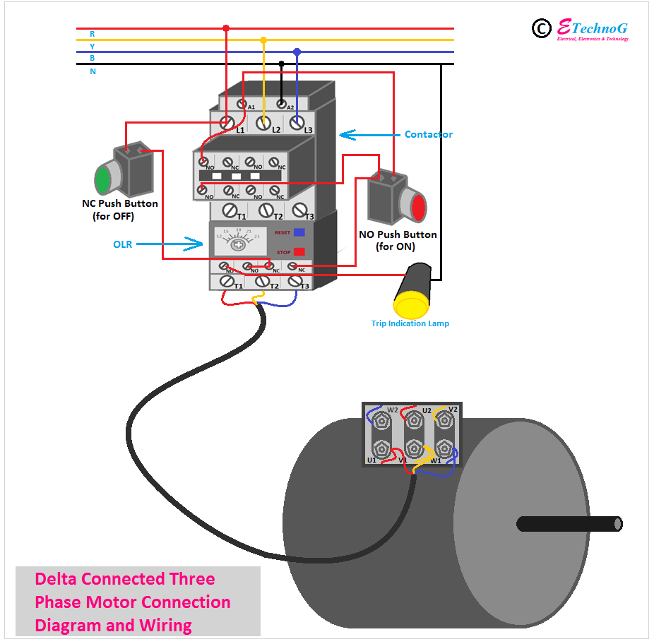
In a delta connection, the ending of a winding is to be connected to the starting of the next winding. So, you can see in the above diagram U2 is connected to V1, V2 is connected to W1, and W2 is connected to U1. And the three-phase power supply is to be connected to the U1, V1, and W1.
Three(3) Phase Motor Wiring in STAR Connection
Here, you can see the wiring of a three-phase motor in the star connection.
Connection and Wiring Procedure
1. Find out the terminals of each winding of the motor.
2. Connect any one terminal of each winding together, here in the above diagram U2, V2, and W2 are connected together.
3. Connect the R phase of the power supply to the U1 terminal of the motor.
4. Connect the Y phase of the power supply to the V1 terminal of the motor.
5. Connect the B phase of the power supply to the W1 terminal of the motor.
Three-Phase Motor Wiring in Delta Connection
Here, you can see the wiring of a three-phase motor in the delta connection.
Connection and Wiring Procedure
1. Find out all the pairs of the terminals of each winding of the motor.
2. Connect all the terminals of the motor in the way that the ending of a coil is to be connected to the starting of the next coil. See the above diagram for a better understanding.
3. Connect the R phase of the power supply to the U1 terminal of the motor.
4. Connect the Y phase of the power supply to the V1 terminal of the motor.
5. Connect the B phase of the power supply to the W1 terminal of the motor.
How to Change the Direction of the Motor?
It is very easy to change the direction of rotation of the three-phase motor. You just need to interchange any two phases of the incoming power supply with the motor.
Read Also:


