Rheostat Symbol, Diagram, and Connection
A rheostat is nothing but a variable resistor. The main function of a rheostat is to control the flow of current by controlling the value of resistance. By increasing or decreasing the resistance value we can increase or decrease the flow of current. Here, we are going to see the construction, connection diagram, and symbol of rheostat.
Generally, rheostats are used for high voltage and high current applications such as DC motor control, light dimming, heater control, etc. The working principle of rheostat is very simple. According to the ohms law, the flow of current depends upon two factors - voltage and resistance. So either by controlling the voltage or controlling the value of resistance we can control the flow of current. So the rheostat does the same. By moving the wiper we can increase or decrease the resistance value to control the flow of current.
Rheostat Symbol
The symbol of rheostat is the same as a normal resistor symbol including an arrow. This arrow indicates the movable wiper or variable resistance.
Read Also:
Rheostat Diagram
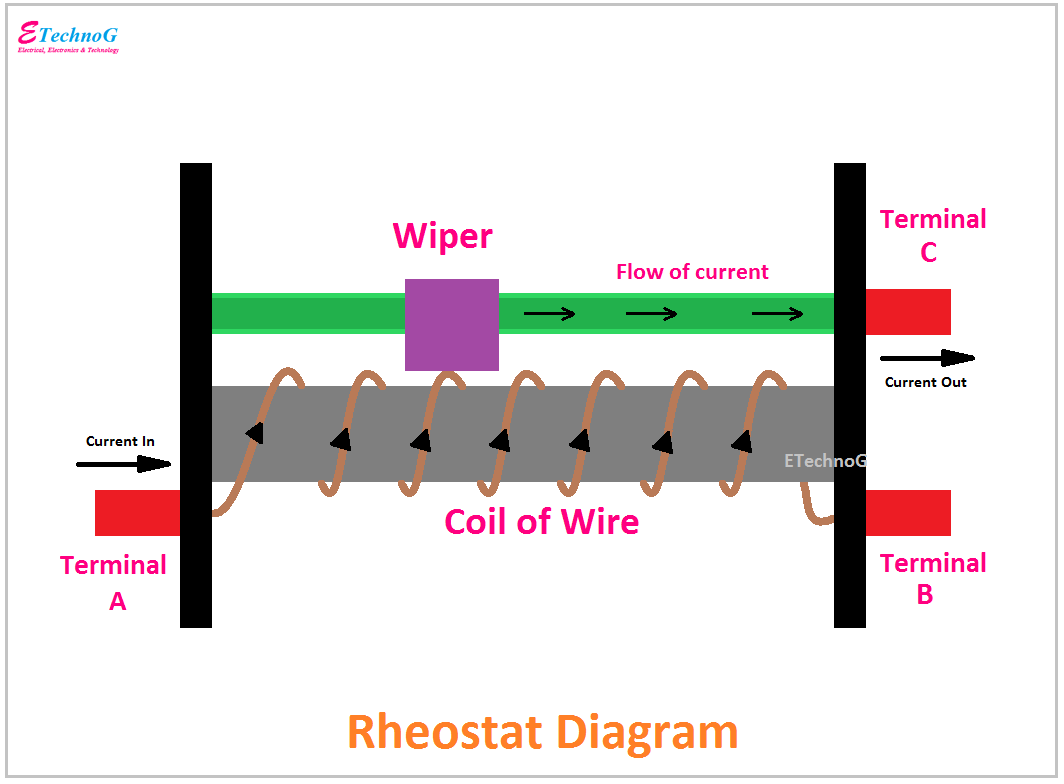
Here, you can see the simple constructional diagram of Rheostat.
The rheostat has a total of three terminals. two terminals are connected to the starting and end of the coil. Another terminal is connected to the metallic path at which the wiper moves.
In the above diagram, you can see the coil is wound on an insulating material. The two terminals of the coil are connected to Terminal A and Terminal B. Terminal C is connected to the metallic path on which the wiper moves. So when we move the wiper, we will get different resistance values between terminal A and terminal C.
Remember that this coil is not insulated. By moving the wiper we mainly increase or decrease the turns. So, increasing the turns means resistance will increase, and decreasing the turns means resistance will decrease. So, when the resistance increases the flow of current will be decreased, and when the resistance decreases the flow of current will be increased.
Read Also:
Rheostat Connection
Here you can see the connection of rheostat.
We already know that rheostat has a total of three terminals. Terminal B is not to be connected anywhere. Keep it disconnected. We only use terminal A and terminal C. The connection of rheostat is very simple. It just has to be connected in series between the power supply and load. When we move the wiper the flow of current from the power supply to the load also be varied.
Also, you can use the B terminal instead of the A terminal. Here, the connection should be between B and C. When you connect the B terminal instead of A, the movement of the wiper should be changed. If you before moved the wiper left to right now you have to move right to left.
There are also disadvantages and safety hazards of using the rheostat. As the coil of wire is not insulated so there is a risk of electrical shock if accidentally touched. The controlling of flow of current using a rheostat causes a huge electrical power loss and unwanted heating.
The working principle of rheostat and potentiometer is almost the same. A potentiometer is used as a voltage divider and all the terminals of the potentiometer are used to connect with a circuit. But in the case of the rheostat, only two terminals are used to connect with a circuit. A rheostat can be used for a Voltage divider circuit by using all three terminals.
Read Also:


